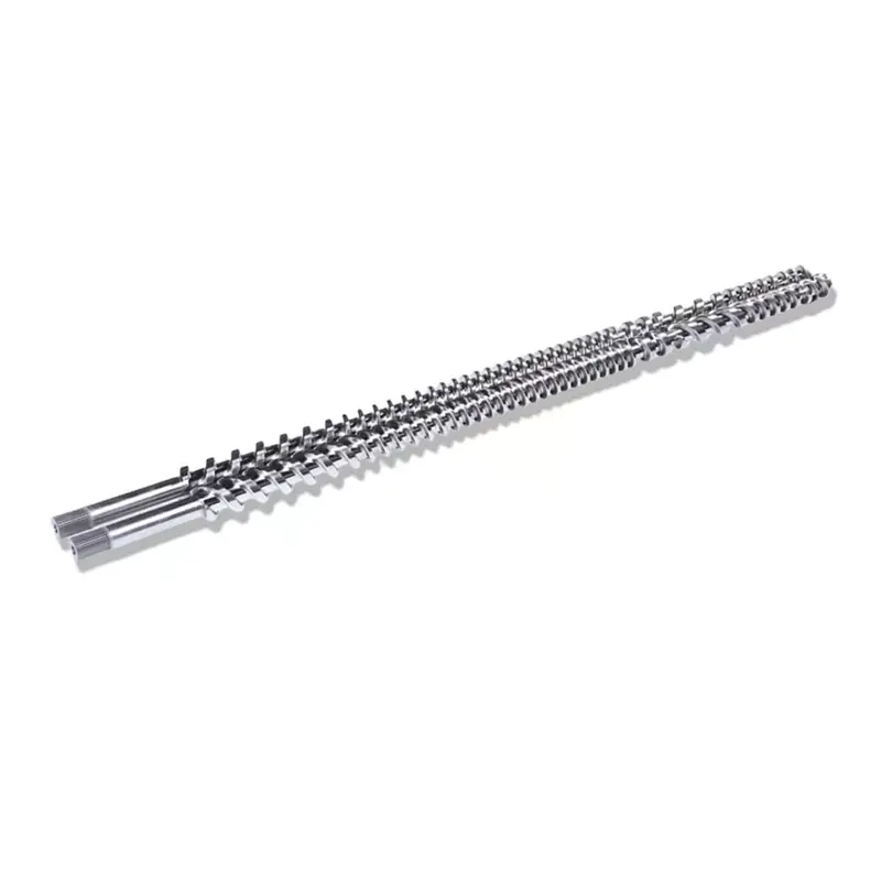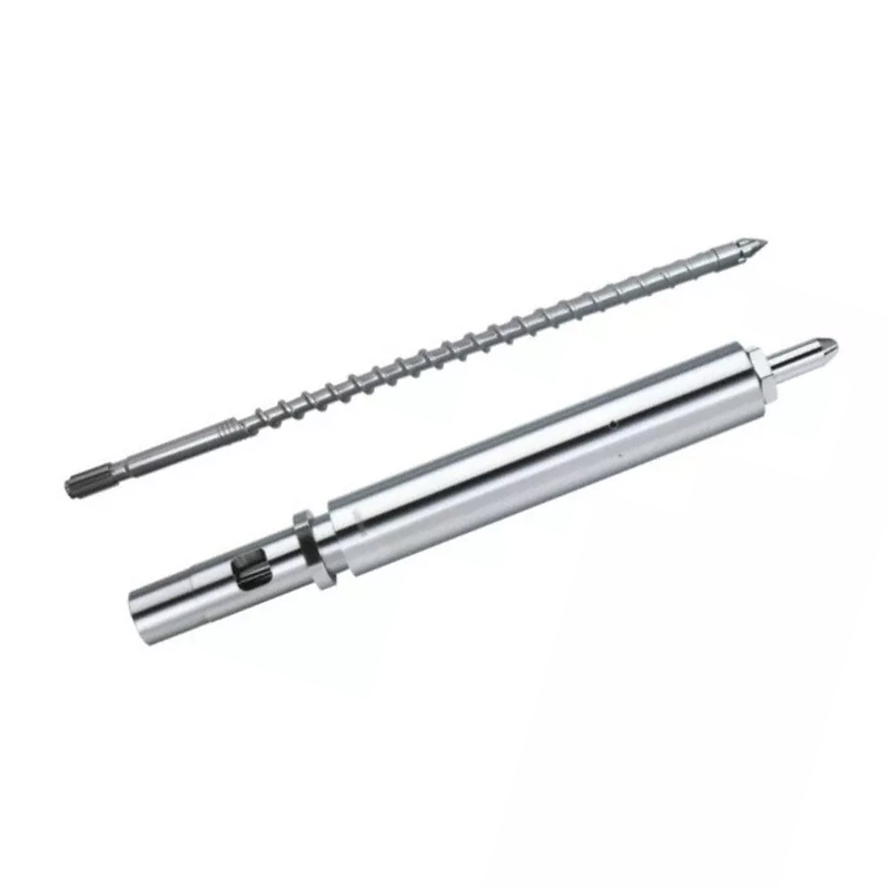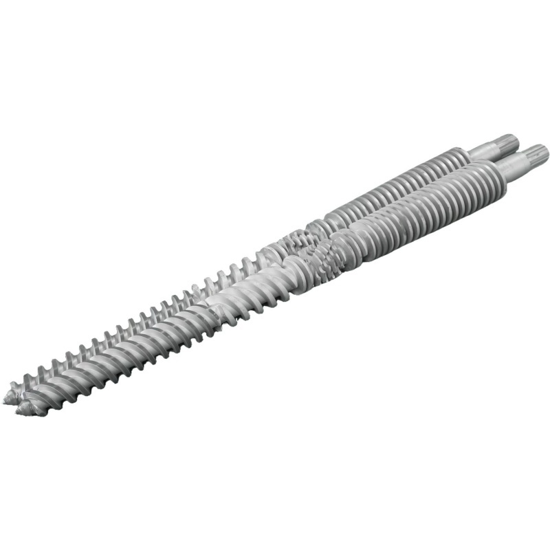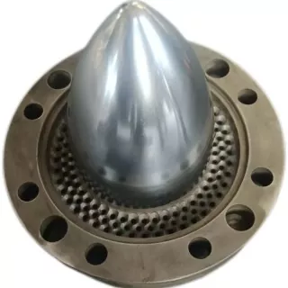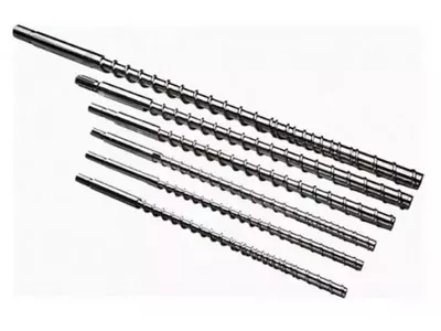

Your injection molding screw barrel decides melt quality, shot consistency, and cycle time. Below: how to select geometry and surface treatment for your resin, how to maintain the set, and how to trace a defect back to the screw, the barrel, or the check ring instead of chasing it through machine settings. Our nitrided 38CrMoAlA injection screws carry a 0.5–0.8 mm nitrided layer at 950–1050 HV, suit PE, PP, PS, and ABS, and handle glass fibre up to 30%. Past that, or on corrosive resin, the bore needs hard-alloy spraying to 62 HRC. If output dropped and cycles stretched, read the troubleshooting table before touching another setpoint.
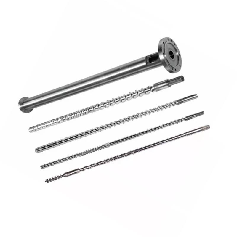
What Is an Injection Molding Screw Barrel?
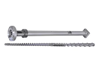
The screw and barrel form the plasticizing unit of the injection molding machine. Together, they take solid pellets from the hopper, melt them, mix them into a uniform melt, meter an exact shot, and inject that shot into the mold. Every part your machine produces passes through this pair.
Molders replace nozzles, tune molds, and adjust temperatures for weeks before they look at the plasticizing unit. That order is backwards. When the screw or barrel wears, no setpoint on the controller brings the process back.
The Role of the Screw in Plasticization
The screw does most of the melting, and not with the heater bands. Barrel heat contributes, but the dominant melting mechanism is shear heat: the screw drags polymer against the hot barrel wall, and the friction generates heat inside the material itself. That is why screw geometry changes melt temperature even when your setpoints do not move.
The screw also meters the shot. It rotates to plasticize, retracts as melt collects in front of the tip, then stops. The distance it is retracted is your shot size. Any melt that leaks backward over the flights or past the check ring corrupts that measurement.
Finally, the screw injects. It stops rotating and drives forward like a plunger, forcing melt through the nozzle. This dual role, rotating and reciprocating, separates an injection screw from an extrusion screw.
The Role of the Barrel in Heat Transfer and Containment
The barrel is a precision pressure vessel with a heated bore. It contains injection pressure, transfers heat from the bands into the polymer, and provides the hard wall against which the screw shears material against.
Its bore must stay round, straight, and dimensionally tight. When the bore wears oversize, the clearance between screw flight and barrel wall grows. Melt then leaks backward over the flights instead of moving forward, and plasticizing rate falls.
Barrel heating is zoned, usually feed, compression, and metering, each with its own controller and thermocouple. A drifted thermocouple in one zone can cook material for months while the display reads normal.
How Screw and Barrel Work Together as a System
The two parts perform as a matched pair, and the number that describes the pair is radial clearance: half the difference between barrel bore diameter and screw flight diameter.
Clearance is small by design. The industry rule of thumb for a new set is roughly 0.001 inch of clearance per side for each inch of screw diameter. On a 60 mm (about 2.36 in) screw, that lands near 0.06 mm per side. Your build drawing is the authority, and it should always be the number you check against.
That small gap does real work. It forces the polymer to shear against the barrel wall instead of slipping past. Double the clearance and the shearing weakens, melting slows, output drops, and the machine tries to compensate with heat it should not need.
Replacing one part alone rarely fixes a worn pair. A new screw inside a worn barrel restores only half the lost clearance, and the mismatch wears the new part faster than it should.
Anatomy of an Injection Molding Screw
A standard injection screw divides into three zones plus a tip assembly. Each zone has a job, and each fails in a way you can recognize.
| Zone | Channel depth | Job | What failure looks like |
|---|---|---|---|
| Feed | Deep | Take in pellets, convey them forward | Bridging, starving, erratic feed, inconsistent recovery |
| Compression (transition) | Shallowing | Compact and melt the polymer against the barrel wall | Unmelts, poor mixing, this zone wears first |
| Metering | Shallow | Homogenize and pump a consistent melt | Shot variation, temperature spikes |
| Tip and check ring | — | Seal against backflow during injection | Shot size drift, short shots, cushion loss |
Feed Zone
Deep channels grab pellets from the hopper throat and move them forward as solids. This zone does not melt much. It conveys.
Feed problems masquerade as melting problems. If pellets bridge in the throat, or the feed section runs too hot and pellets soften and stick early, the screw starves. Recovery time swings, and shot size follows. Check feed-throat cooling before you blame the geometry.
Compression (Transition) Zone
The channel gets shallower along this section. That shallowing squeezes the polymer against the hot barrel wall and generates the shear heat that does the melting.
The compression zone is where wear concentrates. Pressure peaks here, and abrasive fillers grind hardest here. When you measure a worn screw, this is where you find the numbers first.
Metering Zone
Shallow, constant-depth channels homogenize the melt and pump it forward at steady pressure. This zone determines shot-to-shot consistency.
Metering-zone wear shows up as shot variation and rising melt temperature at the same setpoints. The screw is working harder to move the same material.
Screw Tip, Check Ring & Non-Return Valve
The check ring assembly, sometimes called the non-return valve, deserves more attention than it gets. It sits at the screw tip and does one job: during injection it seals, so melt goes into the mold instead of back over the screw.
When it stops sealing, you get shot-size variation, short shots, and a disappearing cushion. Molders spend weeks adjusting injection pressure, hold time, and temperature chasing this. None of it works, because the melt is escaping backward past a worn ring.
Three signals point at the check ring specifically. Cushion varies shot to shot rather than staying constant. Shot weight drifts while the machine reports normal recovery. And a repeatable process suddenly turns erratic without a change in resin or setting.
Key Screw Geometry Parameters
Four numbers describe an injection screw. Understand them, and a supplier's quote stops being a black box.
L/D Ratio: Definition, Formula, and Recommended Values by Resin
L/D ratio is the working length of the screw divided by its outside diameter. A screw 22 times longer than it is wide has an L/D of 22:1. The formula is simply L divided by D, and the ratio scales with size: a 50 mm screw at 22:1 has a 1,100 mm working length.
L/D controls how much room the screw has to melt, mix, and homogenize. Longer gives more melting capacity and better mixing. Shorter gives less residence time, which protects heat-sensitive resins.
Injection screws run shorter than extrusion screws. The screw prepares one shot at a time rather than pumping continuously, and material sits in the barrel between shots. In L/D ratio injection molding practice, most machines fall between 18:1 and 25:1, with 20:1 to 22:1 common on general-purpose machines.
Heat-sensitive resins such as PVC favor the shorter end, so material spends less time hot. Engineering plastics that need thorough melting favor the longer end. Our L/D ratio guide covers the trade-offs in depth.
Compression Ratio: How It Affects Shear Heat and Melt Quality
Compression ratio compares the channel depth in the feed zone to the channel depth in the metering zone. A screw with a feed channel three times deeper than its metering channel has a compression ratio of 3:1.
Compression ratio sets how hard the screw works the material. Higher compression means more shear, more mechanical heat, and more aggressive melting. Lower compression treats the polymer gently.
Match it to the resin, not to a preference for a bigger number. Low-viscosity polyolefins need positive shear to melt cleanly. Heat-sensitive resins such as PVC, PC, and POM degrade under shear that PE would shrug off. Our compression ratio guide works through the ranges.
Flight Depth, Channel Width, and Their Impact on Output
Compression ratio is a ratio, and two screws with the same ratio can behave differently. The absolute depths matter.
A deep metering channel moves more material per revolution, raising plasticizing rate, but it mixes less thoroughly and delivers a less uniform melt. A shallow metering channel mixes better and delivers a more consistent temperature, at lower output per turn.
Flight width and helix angle affect conveying efficiency and the shear the material sees at the flight land. These are design details you specify by describing your process to a screw designer, not numbers you should pick from a table.
Screw Diameter and Shot Size Relationship
Screw diameter sets the machine's shot capacity. A larger screw displaces more volume per millimeter of forward travel, so it delivers a bigger shot.
The practical rule is a comfort band, not a hard limit. Run a shot that uses a small fraction of the barrel's capacity and the material sits in the barrel too long, cycling through heat and degrading. Run at nearly full capacity and you lose the cushion needed for consistent packing.
Most molders target a shot somewhere in the middle of the barrel's usable range. If your part sits outside that band, the correct fix is a different screw diameter, not a harder machine setting.
Here is our published dimension table, which shows how shot capacity tracks screw and barrel size across the range we build. Use it to locate your machine, or to sanity-check the diameter a supplier is quoting you.
| Shot (g) | Screw Ø × length (mm) | Barrel Ø × length (mm) |
|---|---|---|
| 30–90 | Φ30 × 900 | Φ85 × 860 |
| 60–125 | Φ35 × 910 | Φ85 × 860 |
| 100–150 | Φ38 × 935 | Φ95 × 900 |
| 125–160 | Φ40 × 980 | Φ95 × 910 |
| 125–300 | Φ42 × 1030 | Φ105 × 1110 |
| 250–400 | Φ45 × 1210 | Φ115 × 1165 |
| 300–500 | Φ50 × 1300 | Φ125 × 1260 |
| 450–600 | Φ55 × 1335 | Φ130 × 1320 |
| 500–700 | Φ56 × 1350 | Φ130 × 1350 |
| 500–700 | Φ60 × 1380 | Φ140 × 1350 |
| 650–800 | Φ65 × 1415 | Φ150 × 1420 |
| 700–1000 | Φ70 × 1790 | Φ160 × 1685 |
| 80–125 | Φ75 × 1825 | Φ170 × 1725 |
| 100–150 | Φ80 × 2000 | Φ180 × 1805 |
| 125–200 | Φ85 × 2300 | Φ190 × 1900 |
| 200–300 | Φ90 × 2700 | Φ210 × 2000 |
| 250–500 | Φ100 × 2600 | Φ230 × 2405 |
| 300–600 | Φ110 × 2600 | Φ256 × 2590 |
| 400–1000 | Φ120 × 2800 | Φ256 × 2800 |
| 600–800 | Φ130 × 3010 | Φ256 × 2970 |
| 800–1000 | Φ145 × 3010 | Φ256 × 3200 |
| 1000–1500 | Φ160 × 3500 | Φ270 × 3200 |
| 1300–2500 | Φ170 × 3415 | Φ317 × 3380 |
Two things to read out of it. Shot capacity climbs with diameter, as the physics demands. And the barrel outside diameter grows with it, which is why a bigger screw is never a free upgrade: it is a different machine size class.
Types of Injection Molding Screws: Which One Do You Need?
Five screw families cover almost every injection application. The right one depends on your resin and what your part demands.
| Screw type | What it does | Best for | Weakness |
|---|---|---|---|
| General purpose (GP) | Single flight, three standard zones | PE, PP, PS, ABS, most commodity resins | Compromise geometry; struggles with demanding resins |
| Barrier | Second flight separates solid bed from melt pool | Better melting, higher output, unmelt-sensitive parts | Costs more; overkill on easy resins |
| Mixing / compounding | Adds Maddock or pin mixing sections | Color masterbatch, filled compounds, streak-sensitive parts | Extra shear; wrong for heat-sensitive resins |
| Vented (two-stage) | Decompression zone plus vent port pulls off volatiles | Hygroscopic resins where drying is impractical | Complex; vent can drool if mismatched |
| PVC-specific | Low compression, polished surfaces, no dead spots | Rigid and flexible PVC | Purpose-built; not a general-purpose screw |
General Purpose (GP) Screw: Most Common, Best For?
The GP screw is a compromise, and a good one. It runs PE, PP, PS, and ABS acceptably, which covers most commodity molding. Machine builders ship it as standard because it is the safest default when they do not know what you will run.
The compromise costs you when the resin gets demanding. A GP screw on glass-filled nylon wears fast. A GP screw on rigid PVC degrades the material. A GP screw pushed for maximum output on a thin-wall part delivers unmelts. When any of those describes your process, a purpose-built screw pays for itself in scrap alone.
Barrier Screw: Better Melt Separation and Homogeneity
A barrier screw adds a second flight through the melting zone. That flight physically separates the remaining solid pellets from the melt already formed, and keeps the solids pressed against the hot barrel wall where they continue melting.
Without a barrier, solid particles hide inside the melt pool, insulated from the wall, and can survive to the nozzle as unmelts. With one, melting finishes more completely and more consistently.
The payoff is better melt uniformity at the same or higher output, which shows up as fewer unmelts, tighter shot control, and a wider process window. Molders running thin-wall packaging, optical parts, or anything unmelt-sensitive should ask for one by name.
Mixing / Compounding Screw: For Filled and Color Masterbatch Materials
Mixing screws add a dedicated mixing section, usually near the tip. Maddock (fluted) sections force melt through narrow gaps, breaking up unmelted particles by shear. Pin mixers split and recombine the flow, distributing color and filler.
Use one when color streaking is a quality problem, when masterbatch dispersion matters, or when filler distribution drives part performance. The trade-off is added shear, which makes mixing sections the wrong choice for heat-sensitive resins that are already close to their degradation limit.
Vented / Degassing Screw: For Hygroscopic Resins
A vented screw runs two stages. The first stage melts, then the channel deepens abruptly, dropping the melt pressure to near zero at a vent port cut into the barrel. Moisture and volatiles escape there, often under vacuum. The second stage then repressurizes the melt for injection.
This works for hygroscopic resins where drying is impractical or unreliable. It also carries risk: if the two stages are mismatched, melt pushes out of the vent port instead of gas. A vented screw and a vented barrel must be designed together, which is why they are specified as a set and not retrofitted casually.
PVC-Specific Screw Design: Why Standard Screws Fail with PVC
Rigid PVC punishes a standard screw in two ways at once. It degrades under shear, releasing hydrogen chloride, which then corrodes the steel it is sitting against. Damage begins before the operator sees a defect.
A PVC screw answers both threats. Low compression keeps shear gentle. Polished surfaces and a dead-spot-free geometry stop material from stagnating and cooking. The set almost always needs corrosion resistance in the surface treatment, not only wear resistance. Our PVC screw barrel guide covers the chemistry, and our conical twin screw barrels serve PVC on the extrusion side.
How to Select the Right Screw Barrel for Your Resin
Resin selection drives every other decision on the page: geometry, steel, and surface. Read the table, then read the notes under it, because the notes carry the warnings.
| Resin | Typical L/D | Typical compression ratio | Screw type | Special notes |
|---|---|---|---|---|
| PP / PE | 20:1 – 22:1 | 2.5:1 – 3.5:1 | GP or barrier | Forgiving. Needs positive shear to melt cleanly |
| PS / HIPS | 20:1 – 22:1 | 1.8:1 – 2.5:1 | GP | Low viscosity, melts easily. Gentle mixing on HIPS |
| ABS | 20:1 – 24:1 | 2.0:1 – 2.5:1 | GP or barrier | Amorphous. Watch shear heat, streaks show easily |
| PC and engineering plastics | 22:1 – 25:1 | 2.0:1 – 2.5:1 | Barrier or GP, low shear | High melt temperature, narrow window. Longer L/D, gentle compression |
| PVC rigid | 18:1 – 20:1 | 1.6:1 – 2.5:1 | PVC-specific | Corrosion resistance is not optional. Short residence time |
| PVC flexible | 18:1 – 20:1 | 2.0:1 – 2.8:1 | PVC-specific | More forgiving than rigid, still corrosive |
| PET (preform) | 20:1 – 24:1 | Low, precise metering | Purpose-built PET | Dry it or degrade it. Low shear, minimal residence, polished surfaces |
| POM (acetal) | 20:1 – 22:1 | 2.5:1 – 3.5:1 | GP, low shear | Degrades sharply if overheated. Precise temperature control |
| Glass-filled / abrasive | Per base resin | Per base resin | Base type + hard surface | Geometry follows the base resin. The surface is what changes: go bimetallic |
How to use this table: these are typical published ranges and starting points, not specifications. Your machine, your grade, your part, and your output shift the numbers. A screw designer confirms the final geometry against your real process. Never order from a generic table without that conversation.
PP and PE: Semi-crystalline, Moderate Shear
Polyolefins are the easy case. They tolerate shear, melt over a broad window, and forgive a GP screw. Moderate to higher compression works well, because these low-viscosity resins need positive shear to melt cleanly rather than slipping through half-molten.
Push output hard on thin walls, and a barrier screw earns its cost by delivering a more complete melt at the same speed.
ABS and PS: Amorphous, Watch the Shear Heat
Amorphous resins soften over a range rather than melting at a sharp point. PS runs at low compression because it melts so easily. ABS needs more care: it shows streaks and splay when it degrades, and shear heat is usually the reason.
If ABS parts streak and your setpoints look correct, suspect shear before you suspect the dryer. An aggressive compression ratio on a heat-sensitive amorphous resin manufactures its own defects.
PC and Engineering Plastics: High Temperature, Longer L/D
PC, nylon, PBT, and their relatives melt high and degrade close above that. They need thorough melting, which argues for a longer L/D, but they also punish residence time, which argues against holding melt in a big barrel.
The resolution is longer L/D with gentle compression and a correctly sized shot. Get the shot size wrong on PC and material cycles through heat until it yellows, no matter how good the screw is.
PVC Rigid and Flexible: Corrosion Resistance Critical
Everything above about PVC applies to selection. Rigid PVC sits at the low end of both L/D and compression, because time and shear are both enemies. The surface treatment must resist corrosion, not just abrasion, and that changes the alloy choice inside a bimetallic barrel.
PET and POM: Low Shear, Precise Temperature Control
PET is hygroscopic. Water in the melt hydrolyzes the polymer chains, drops intrinsic viscosity, and leaves preforms brittle and hazy while the machine looks like it is running fine. Dry the resin properly, run low shear, keep residence short, and specify polished surfaces so deposits do not form.
POM tolerates ordinary compression but degrades sharply when overheated, and its degradation products are hazardous. Temperature control and residence time discipline matter more than clever geometry.
Glass-Filled and Abrasive Materials: The 30% Line
Here is the clearest rule on the page, and it is a number, not a feeling. Glass fibre up to 30%: a nitrided 38CrMoAlA set handles it. We build and rate our nitrided injection screws for exactly that, quenched and tempered, then gas-nitrided to a 0.5–0.8 mm case at 950–1050 HV.
Above 30% glass, or with mineral filler and flame retardant on top, the surface has to change. The nitrided case is a diffusion layer, and abrasive filler cuts through it far sooner than the steel underneath deserves.
That is when a bimetallic screw barrel stops being an upgrade and becomes the correct specification: hard alloy sprayed the full circle around the bore's wear zone, taking the inside hardness to 62 HRC. The geometry still follows the base resin. Only the surface changes. Our bimetallic vs nitrided guide works through the cost logic.
Barrel Types, Materials, and Surface Treatments
The barrel does not fail dramatically. It opens up, quietly, and takes your output with it. Material and surface decide how long that takes.
Standard Nitrided Steel Barrel: Applications and Limits
Nitriding diffuses nitrogen into the steel surface, forming a hard case. We gas-nitride our 38CrMoAlA injection screws at 500–560 °C, producing a nitrided layer 0.5–0.8 mm thick at 950–1050 HV. That raises wear resistance by 30–40% over the untreated steel.
The base steel is quenched and tempered first, which lifts shear wear resistance by 50% on its own. Together, those two steps give a service life of roughly 10,000–20,000 hours on non-corrosive resins such as PE and PP.
Its limit is the case depth. Once abrasion cuts through the nitrided layer, the softer core underneath wears fast. We rate our nitrided injection screws for glass-fibre-reinforced compounds up to 30% (PA plus glass fibre, for example). Above that, or on corrosive resins, the nitrided case is outmatched and the surface has to change.
Bimetallic Barrel: Construction, Cost, and When It Pays Off
A bimetallic barrel keeps an alloy-steel body and fuses a separate wear alloy into the bore. On our barrels we spray hard alloy around the full circle of the bore's wear zone, bringing the inside hardness to 62 HRC.
That is a different kind of protection from nitriding. A nitrided case is a diffusion layer measured in fractions of a millimetre. A sprayed or fused alloy bore is a layer of different metal, and abrasive filler has to get through all of it.
The alloy is selected for the threat. Carbide-rich and tungsten-carbide surfaces resist abrasion from glass and mineral fillers. Nickel-bearing alloys resist corrosion from PVC and flame-retardant compounds. Choose the wrong alloy and you have paid for a bimetallic barrel that solves the wrong problem.
It pays off whenever your feed is abrasive or corrosive. The arithmetic is simple: if a bimetallic set lasts several times as long as a nitrided one on your material, the higher purchase price divides down to a lower cost per year, before you count the scrap and downtime you avoid.
Segmented vs Monolithic Barrel: Flexibility vs Precision
A monolithic (one-piece) barrel is machined from a single body. It holds straightness and concentricity best, and it is the norm for injection molding, where precision drives shot consistency.
Segmented barrels bolt together from sections, which allows a worn section to be replaced without scrapping the whole barrel, and allows vent ports to be positioned flexibly. The trade is alignment: every joint is an opportunity for misalignment, and injection machines are less forgiving of that than compounding extruders.
Base Steel and the Surface Options That Sit on It
38CrMoAlA is the base steel we machine our injection screws from, and it is the industry's default for a reason. Its chromium-molybdenum-aluminium chemistry is designed for nitriding: the aluminium forms hard, stable nitrides in the case while the core stays tough.
The base steel carries the mechanical load. The surface on top of it takes the wear, and that is where the real choice lies. As a screw barrel manufacturer we supply the full surface range, and each answers a different threat:
- Nitriding — 0.5–0.8 mm layer at 950–1050 HV. Clean resins, glass fibre up to 30%.
- Bimetallic surfacing — hard alloy fused around the bore's wear zone, bore to 62 HRC. Abrasive and corrosive duty.
- Tungsten carbide spraying — for the hardest abrasion cases.
- Chrome plating — a smooth, release-friendly surface. Helps with colour changes and sticking, not with heavy abrasion.
- Stainless steel — when corrosion resistance or material purity leads the requirement rather than wear.
Our screw barrel materials guide compares the base steels in full.
Surface Treatments Compared
| Material / treatment | Hardness | Wear resistance | Corrosion resistance | Best for |
|---|---|---|---|---|
| 38CrMoAlA, nitrided | 950–1050 HV, 0.5–0.8 mm layer | Good | Moderate | PE, PP, PS, ABS; glass fibre up to 30%. The economical default |
| Bimetallic surfacing | Bore to 62 HRC | Excellent | Good | Glass-filled above 30%, mineral-filled, regrind, abrasive duty |
| Tungsten carbide spraying | Very high | Excellent | Good | The hardest abrasion cases |
| Nickel-base alloy surfacing | Selected per formulation | Good | Excellent | PVC, fluoropolymers, flame retardants |
| Hard chrome plating | Hard, very thin | Moderate | Good | Smooth release, easier colour changes, anti-stick |
| Stainless steel | Per grade | Moderate | Excellent | Corrosion or purity-led applications |
Specify the surface for the dirtiest feed the line will actually run, not the cleanest. Specifying for the clean case is the most common way a new set dies early.
Maintenance: How to Get Every Hour the Set Can Give
Maintenance does not reverse wear. It stops you from adding avoidable wear on top of the unavoidable kind, and it gives you the data to plan the replacement instead of reacting to it.
Routine Inspection Checklist
| Frequency | What to check | Why |
|---|---|---|
| Every shift | Melt temperature vs normal, recovery time, cushion consistency, motor load | These drift before defects appear |
| Every material or color change | Purge fully; inspect purge for black specks or degraded material | Specks mean dead spots or degradation somewhere |
| Monthly | Verify thermocouples and heater bands; check feed-throat cooling | A drifted sensor cooks material for months unnoticed |
| Whenever the screw is out | Measure flight OD and barrel bore ID at marked positions; inspect check ring | The screw is already out. Ten minutes of measuring is free data |
| At least yearly (abrasive or corrosive duty) | Planned pull: full wear measurement, alignment check, log the readings | Filled, PVC, and regrind duty wears sets far faster than clean resin |
Proper Purging Procedure When Changing Resins or Colors
Purge before every stop and every changeover, without exceptions for busy days. Material left to cool inside the barrel degrades, bakes onto surfaces, and returns later as black specks in a customer's part.
Use a commercial purging compound for color changes, for shutdowns, and before switching to a heat-sensitive polymer. Virgin PE or PP handles routine transitions between compatible materials. High-temperature resins such as PC and PMMA hold on harder and need more aggressive purging.
Purge before shutting down, not only before starting up. What you leave in a cooling barrel becomes the problem you fight at the next startup.
How to Measure Screw-to-Barrel Clearance
This is the measurement that turns opinion into fact, and most shops skip it.
- Pull and clean the screw. Hot, with brass or copper tools. Never steel scrapers, which cut the treated surface the screw depends on.
- Mark measurement positions along the working length: feed, transition, and metering at minimum.
- Measure flight OD with an outside micrometer at each position, taking readings at several points around the circumference to catch uneven wear.
- Measure barrel bore ID with a bore gauge at matching positions and depths.
- Calculate radial clearance: subtract flight OD from bore ID and divide by two.
- Compare against the build drawing and log every reading with the date and hours run.
Interpret the result against the original clearance, not against a universal number. A useful shop rule: when clearance has grown to roughly twice the build value, or when output has dropped noticeably at the same screw speed, start planning the replacement. Our step-by-step measurement guide covers the method in full detail.
Cleaning Schedule and Purging Compound Types
Match the compound to the job. Mechanical (abrasive-free) purges scrub with high viscosity. Chemical purges attack degraded material and carbon. Foaming purges expand to reach dead spots that laminar flow misses.
Deep-clean intervals depend on the resin. High-temperature polymers build carbon faster and need more frequent deep purging. Whatever you run, keep the interval on a schedule rather than waiting for black specks to schedule it for you.
When to Repair vs When to Replace
Compare cost per year of service, not the two price tags. A rebuild that costs half as much but returns a third of the years is the expensive option in disguise.
Repair leans right when wear is dimensional and moderate, the base metal is sound, this is the first rebuild, and the geometry still suits your resin.
Replacement leans right when corrosion has pitted deep, when the screw has already been rebuilt before, when your material changed and the old geometry no longer fits, or when the set is a common size whose replacement price sits close to the repair quote.
Our repair vs replacement guide lays out the full decision table.
Proper Storage and Handling of Spare Screw Barrels
A spare set is only useful if it is straight and clean when you need it. Store screws horizontally with support along the length, never leaning on the tip. Coat them against rust, keep them covered, and keep the spec sheet and measured hardness figures with the part.
The spare-set rotation strategy is worth more than any expedite fee, and almost no supplier will tell you this. Buy the replacement before the current set fails. Run the new set, send the old one for rebuild while production continues, and keep the rebuilt set on the shelf as the spare.
You now own a rotation with zero unplanned downtime, and every future replacement happens on your schedule instead of at 2 a.m. on a Saturday. The strategy costs one set of working capital and repays it the first time a breakdown does not happen.
Is It the Process or the Machine? A Decision Gate
Here is the section no competitor writes, and it will save you more time than the rest of this guide combined.
When a molding defect appears, most teams reach for the machine settings. Temperature, back pressure, injection speed, hold time. Sometimes that is right. But when the plasticizing unit is worn, no setting recovers the process, and weeks disappear into a search that could never succeed.
Run this gate before you touch another setpoint.
1. Did anything change? New resin lot, new colorant, new regrind ratio, new mold, a setting someone adjusted? If yes, chase the change. This is a process problem until proven otherwise.
2. Did the defect appear suddenly, or creep in over weeks? Sudden points at a change or a broken component. Gradual points at wear. Wear does not arrive overnight.
3. Is the cushion consistent shot to shot? An inconsistent cushion is the check ring talking. Inspect it before anything else.
4. Has output dropped at the same screw speed, or has recovery time stretched? Both point at clearance, meaning screw or barrel wear. Settings cannot restore lost clearance.
5. Is melt temperature climbing at unchanged setpoints? The screw is generating extra shear heat, usually because it is working harder against a worn clearance.
6. Do black specks return after every cleaning? Material is lodging in a dead spot. On an older set, that dead spot is often worn clearance harboring degraded melt.
Three or more “yes” answers on questions 3 through 6 mean the machine is telling you the plasticizing unit is worn. Stop tuning. Pull the screw and measure it.
The measurement takes an hour. Chasing a mechanical defect through the settings takes weeks, and it never converges, because the answer was never in the controller.
Troubleshooting Guide with Root-Cause Table
Each defect below can come from process or from mechanical wear. The table names the screw and barrel root cause, because that is the half everyone else leaves out.
| Problem | Symptom | Screw / barrel root cause | Corrective action |
|---|---|---|---|
| Black streaks / burn marks | Dark specks or streaks in the part; worse after a stop | Degraded material lodged in worn clearance or a dead spot; scored bore; damaged screw surface | Deep purge. If specks return, pull and inspect. Check for scoring and worn clearance. Replace if the set is harboring material |
| Inconsistent shot size / short shots | Shot weight drifts; cushion varies shot to shot | Check ring not sealing (most common); worn flights letting melt leak backward; barrel bore oversize | Inspect the check ring first. Then measure clearance. Settings will not fix a leaking non-return valve |
| Melt temperature spiking | Actual melt temperature above setpoints; material discoloring | Excessive shear from wrong compression ratio; worn clearance making the screw work harder; drifted thermocouple | Verify thermocouples. Check screw speed and back pressure. If geometry is wrong for the resin, the screw is the fix |
| Slow recovery / long plasticizing | Recovery time stretches; cycle time grows | Worn clearance reducing pumping efficiency; feed section issue; wrong geometry for the resin | Check feed-throat cooling and pellet feed first. Then measure clearance against the drawing |
| Rising motor load / back pressure | Motor amps climbing at constant output; torque alarms | Screw dragging in the bore (misalignment, bent screw); excessive shear; degraded material building resistance | Check alignment and screw straightness. A bent screw wears one side of the bore and will destroy a new barrel too |
| Material degradation / discoloration | Yellowing, splay, brittleness, smell | Residence time too long (shot too small for the barrel); shear too aggressive; dead spots holding material | Check shot-size to barrel-capacity ratio. Reduce shear. On heat-sensitive resins, a lower-compression screw may be the only real fix |
| Unmelts / solid particles in part | Hard specks; lens-like defects; weak spots | Insufficient melting capacity: L/D too short, compression wrong, output pushed past what the screw can melt, or worn clearance | Reduce output or upgrade to a barrier screw. If the set is worn, no setting recovers the melting |
| Color streaking / poor dispersion | Uneven color; masterbatch not dispersing | No mixing section; worn screw mixing poorly; wrong screw for a filled or colored compound | Specify a mixing section (Maddock or pin). Confirm the screw is not simply worn out first |
Black Streaks or Burn Marks
Degraded polymer is lodging somewhere and breaking loose in pieces. The classic hiding places are worn clearance, a scored bore, a damaged check ring, and any dead spot where flow stagnates.
Deep purge first. If the specks come back after a thorough purge, the material is not simply residue. It is being manufactured continuously by a spot in your machine, and you need to pull the screw and find it.
Inconsistent Shot Size or Short Shots
Check the ring before you touch a setting. When the non-return valve stops sealing, melt escapes backward during injection, and the shot the machine thought it measured is not the shot the mold receives.
The giveaway is the cushion. A consistent process holds a steady cushion. When cushion wanders shot to shot, melt is going somewhere it should not.
Melt Temperature Spiking or Too High
Measure the actual melt with a probe rather than trusting the setpoints. If actual melt runs well above the zones, the extra heat is coming from shear, not from the bands.
Shear heat rises when compression is too aggressive for the resin, when screw speed is too high, when back pressure is excessive, and when a worn screw has to work harder to move the same material.
Slow Screw Recovery / Long Plasticizing Time
Start at the hopper. Bridging pellets, an overheated feed throat, and inadequate feed cooling all starve the screw and stretch recovery, and none of them are a screw defect.
If feed is healthy and recovery is still slow, measure the clearance. A screw that has lost its pumping efficiency to wear takes longer to fill the same shot, and the cycle time reflects it.
Rising Motor Load or Back Pressure
Rising amps at constant output means something is resisting. A bent screw dragging in the bore is the dangerous case: it wears one side of the barrel, and a new screw installed against that misalignment wears the same way on the same schedule.
Check straightness and alignment before you order anything. One-sided bore wear is the fingerprint.
Material Degradation or Discoloration
Two causes dominate: the material is too hot, or it has been hot for too long. The second is the one people miss.
A shot that is far too small for the barrel leaves melt sitting through cycle after cycle, cooking gently until it yellows. No screw design fixes an undersized shot in an oversized barrel. Correct the screw diameter, or move the job to a smaller machine.
How to Order a Replacement Screw Barrel
No competitor covers this, and it is the part buyers actually need. Whether you order from the OEM or from an independent screw barrel factory, the same information drives the quote.
Dimensions and Specifications You Must Provide
- Machine brand and model. A nameplate photo is enough to confirm the mounting and drive-end dimensions.
- Screw diameter and L/D ratio, from a drawing or measured directly.
- The resin, with filler content. This drives the base steel and the surface treatment more than anything else on the list.
- Shot size and target cycle, so the geometry can be optimized rather than copied.
- A drawing, or a worn sample. Either works. A worn part can be measured and the full geometry reconstructed.
- What went wrong last time. Send the wear pattern along with the part. Smooth dimension loss says abrasion. Pitting says corrosion. One-sided wear says alignment, which a new screw will not fix.
That last item is the one buyers forget, and it is the one that stops you buying a faithful copy of a failure.
OEM-Match vs Custom Design: Pros and Cons
An OEM match reproduces the original geometry. It is the right call when the original screw suited your process and simply wore out. Predictable, verifiable against the drawing, no process revalidation.
A custom design changes the geometry to fit what you actually run today. It is the right call when the process moved and the screw did not: you added regrind, switched to a filled grade, changed output targets, or the original screw never handled your resin well.
Ordering an OEM match when the process has changed reproduces the problem in new steel. Ordering a custom design when the original was fine adds cost and revalidation for nothing. The wear pattern tells you which situation you are in.
What to Expect When Sourcing from China
Lead time depends on the geometry, the surface treatment, and whether a drawing exists. Ask for it in writing with your quote, and ask what the clock starts on: confirmation of the drawing, or the purchase order. They are not the same date, and the difference is often a week.
Three things worth pinning down before you commit:
- When production starts. Reverse-engineering a worn sample adds time before a single chip is cut. A drawing removes that step.
- What the surface treatment adds. Bimetallic surfacing and carbide spraying are separate process steps with their own queue.
- Sea freight, separately. It is not in the manufacturing lead time, and it is the number that surprises first-time buyers.
Our own quoting is transparent by design: we give an estimated cost covering the product, the shipping, and the ongoing maintenance, so there is nothing to discover later. You get that quote within 12 hours.
Plan around lead time with the spare-set rotation described earlier. A set ordered from a wear log ships on your schedule. A set ordered from a breakdown ships against the clock, by air, at a price nobody enjoys explaining.
Quality Acceptance Criteria and Inspection Points
These are the checks that separate a real supplier from a cheap one. Ask for them in writing before you place the order, and verify them when the set arrives:
- Outside diameter at multiple points along each flight
- Bore diameter and cylindricity
- Surface hardness as a measured value (HV or HRC), not a catalogue specification
- Nitrided case depth, or alloy layer depth on a bimetallic bore
- Concentricity and straightness
- Surface roughness (Ra)
- Base steel grade, confirmed
The hardness and the case depth are the two that matter most, and the two most often quietly downgraded. A nitrided layer at 950–1050 HV and 0.5–0.8 mm deep is a specification you can hold a supplier to. “Nitrided” on its own is not.
If a quote lands dramatically below the others, ask what the steel is and how deep the treatment runs. That is almost always where the difference hides, and you pay it back in early wear.
Our full sourcing walkthrough sits in the custom screw barrel order guide.
Need a replacement or custom injection screw barrel? Send your machine model, drawing, or worn sample. We quote within 12 hours.
Get a Screw Barrel QuoteFrequently Asked Questions
Q: How long does an injection molding screw barrel last?
A: On non-corrosive resins such as PE and PP, our nitrided 38CrMoAlA injection screws run roughly 10,000–20,000 hours. Glass-filled compounds, PVC, and heavy regrind cut that down, and how far depends on filler content and output. Do not run the clock and hope: measure. Check flight OD and bore ID against the build drawing at least once a year on abrasive duty, and log the trend. The trend, not an hours figure, tells you when to order the next set.
Q: What is the standard clearance between a screw and barrel?
A: There is no single figure, because clearance scales with screw diameter. The industry rule of thumb for a new set is roughly 0.001 inch of radial clearance per side for each inch of screw diameter, so a 60 mm screw lands near 0.06 mm per side. Your build drawing is the authority. As a practical service limit, when measured clearance has grown to roughly twice the build value, or output has dropped noticeably at the same screw speed, plan the replacement.
Q: Can I use one screw for multiple different resins?
A: Within a family, yes. A general-purpose screw handles PE, PP, PS, and ABS acceptably, which is why machine builders ship it as standard. Across families, no. A GP screw on rigid PVC degrades the material and corrodes the steel. A GP screw on glass-filled nylon wears out fast. And a screw sized for one shot volume cannot serve a job that uses a small fraction of the barrel without cooking the material. If your resins span those gaps, you need more than one screw, or a screw designed for the hardest case.
Q: How can I tell if my injection molding screw is worn?
A: The machine tells you first, and the micrometer confirms it. Watch for output dropping at the same screw speed, recovery time stretching, melt temperature climbing at unchanged setpoints, black specks that return after cleaning, and shot size drifting. Any of those justifies pulling the screw. Then measure flight OD with a micrometer and bore ID with a bore gauge, at matched positions, and compare the radial clearance against the drawing. Symptoms suggest; measurement confirms.
Q: What is a bimetallic screw barrel and when do I need one?
A: A bimetallic barrel keeps an alloy-steel body and fuses a harder wear alloy into the bore. On our barrels we spray hard alloy the full circle around the bore's wear zone, bringing the inside hardness to 62 HRC. The line is easy to draw: glass fibre up to 30% runs fine on a nitrided 38CrMoAlA set. Above 30% glass, with mineral filler or flame retardant, or on corrosive resin, go bimetallic. The nitrided case is a 0.5–0.8 mm diffusion layer, and heavy filler cuts through it long before the steel underneath is finished.
Q: Does screw design affect part quality in injection molding?
A: Directly, and more than most process settings. Screw geometry determines how completely the material melts, how uniform the melt temperature is, how well color and filler disperse, and how consistent the shot is. Unmelts, streaks, splay, degradation, and shot variation all trace back to screw design or screw wear at least as often as they trace back to the controller. When a defect resists every setting change you make, the geometry or the wear is usually the reason.
Q: What is the difference between an injection screw and an extrusion screw?
A: An extrusion screw rotates continuously and pumps melt forward without stopping. An injection screw does two jobs: it rotates to plasticize a shot, then stops rotating and drives forward like a plunger to inject it. That reciprocating action is why injection screws carry a check ring at the tip, and why they run shorter L/D ratios, typically 18:1 to 25:1, than extrusion screws. Material also sits in an injection barrel between shots, which makes residence time and shot sizing critical.
Q: Can a screw barrel manufacturer copy my screw without a drawing?
A: Yes. Ship the worn part and the geometry can be measured and reconstructed: diameter, aspect ratio, channel depth, and the fit dimensions at the drive end. We hold injection screws to ±0.001 mm. One caution worth stating: a worn screw measures smaller than it left the factory, so the replacement should be built to the original design intent rather than to the worn dimensions. Send the wear pattern along with the part, and the new screw gets specified against the failure instead of inheriting it.
Conclusion
Three ideas carry the whole guide.
Selection follows the resin. Geometry (L/D, compression ratio, screw type) matches how your polymer melts. Surface treatment matches how dirty your feed is. Clean resins run happily on nitrided 38CrMoAlA. Abrasive and corrosive feeds need a bimetallic bore, and specifying the clean case is the most common way a new set dies early.
Maintenance buys years, and data buys planning. Purge before every stop, clean with brass rather than steel, and measure the clearance every time the screw is out. A wear log turns “is it worn?” into “when will it cross the line?”, which is the difference between a planned changeover and a shutdown.
Diagnose the machine before you tune the process. When output drops, cycles stretch, the cushion wanders, or specks return after cleaning, the plasticizing unit is talking. Settings cannot restore lost clearance or reseal a worn check ring. Pull the screw and measure it.
Nanhaiya has built screws and barrels for over twenty years and serves 500+ clients worldwide. Our injection screws are machined from 38CrMoAlA, quenched and tempered, then gas-nitrided at 500–560 °C to a 0.5–0.8 mm case at 950–1050 HV, held to a tolerance of ±0.001 mm, and rated for 10,000–20,000 hours on non-corrosive resins. Where the feed is harsher, we spray hard alloy the full circle around the bore's wear zone and take the inside hardness to 62 HRC.
Before you order, our engineers work through the parameters with you: diameter, aspect ratio, screw channel depth, and the material choice between 38CrMoAlA and a duplex alloy. That consultation is free, and the quote that follows includes product, shipping, and expected maintenance cost, so nothing appears later that was not on the page.
After delivery, our technicians support installation and commissioning, warranty runs to contract (usually one to two years), and any after-sales issue gets a response within 24 hours and a solution within 48.
Send us your machine model, resin, and the problem you are trying to solve. You will have a specification and a quote within twelve hours.
Tell us your machine, your resin, and what went wrong last time. We will specify the set that fixes it, not the one that repeats it.
Contact Nanhaiya for a Quote