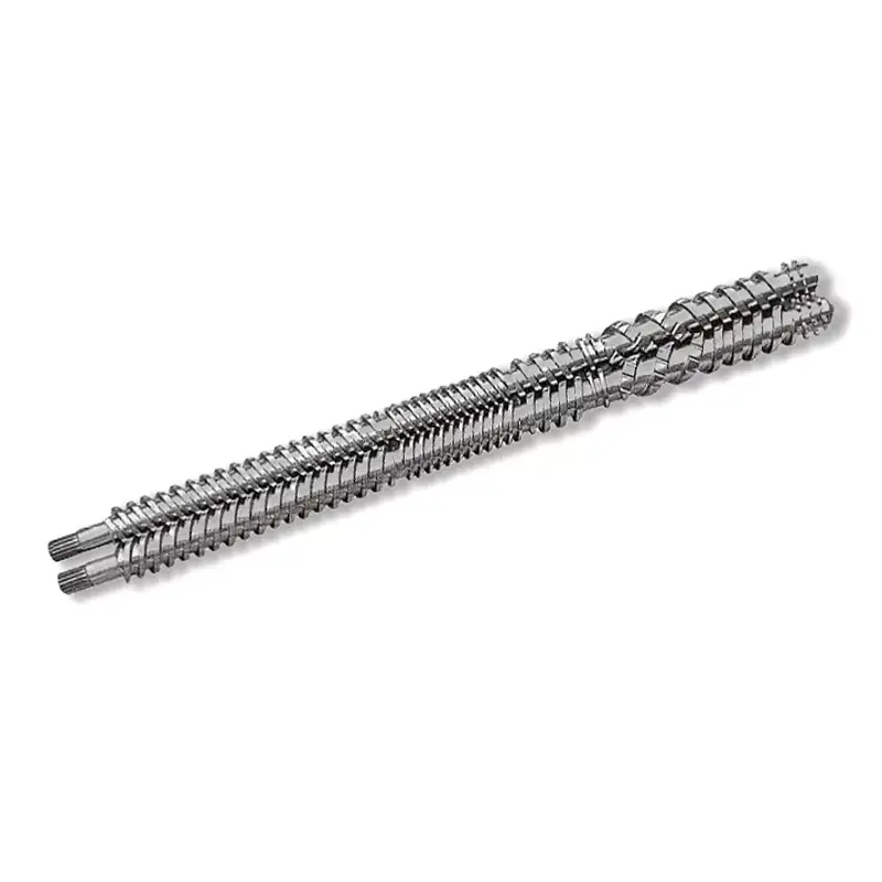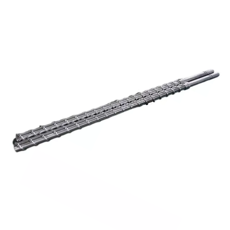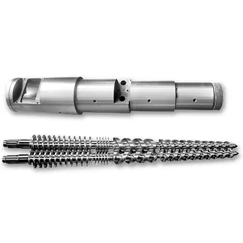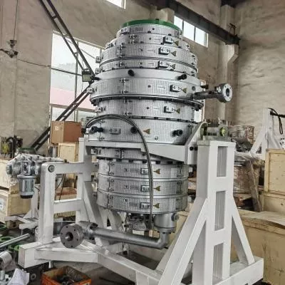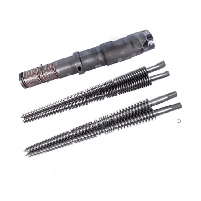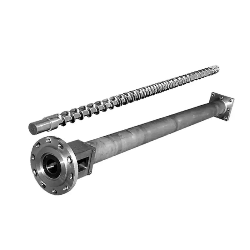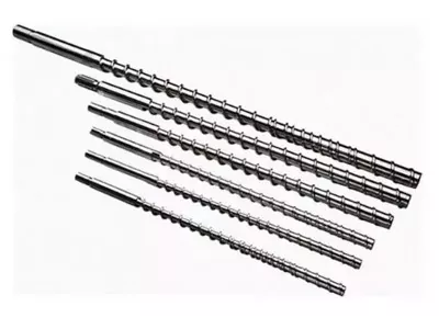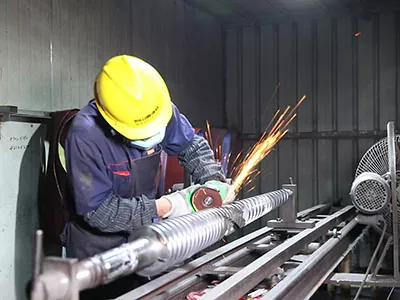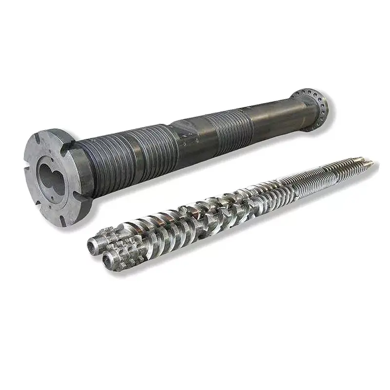

- Separate the screw's machined channel depth from running clearance and the flow-channel height used in a calculation.
- Feed, transition and metering sections have different jobs. One depth rule cannot describe every section.
- Under an opposing pressure gradient, pressure flow reduces the net delivery available from screw rotation.
- Check upstream feeding, melting and wear before changing a metering profile.
- Compare accepted output, melt temperature and drive load together when judging a revised design.
What is channel depth in a plastic extruder screw?
For a component drawing, define machined channel depth as the radial distance from the root to the flight outside-diameter envelope. If Do is that flight diameter and Dr is the root diameter at the same section, the depth is half their difference. The full diameter difference is not the channel depth.
Machined screw depth: Hs = (Do − Dr) / 2
Radial running clearance: c = (Db − Do) / 2
Barrel-to-root height: h = (Db − Dr) / 2 = Hs + c
Db is the matching barrel bore. These relations describe corresponding circular sections.
Read the reference surface before using a depth value
A flow model may define depth from the barrel wall rather than the flight envelope. The Penn State single-screw extrusion notes use barrel-to-root geometry. Here we call that height h, while Hs identifies the machined screw dimension. A supplier's drawing may use different letters; the stated reference surfaces matter more than the symbol.
For an illustrative calculation, assume Do = 65.0 mm, Dr = 57.0 mm and Db = 65.2 mm. Hs is 4.0 mm, c is 0.1 mm and h is 4.1 mm. These assumed dimensions explain the definitions; they are not acceptance values for a Nanhaiya screw.
Record the axial location and measurement condition alongside each value. A normalized H/D ratio is meaningful only when both dimensions use agreed definitions. It cannot establish capacity or pressure capability by itself. Our parameter-matching service includes groove depth, diameter and L/D because all three are needed to review a profile.
Why feed, transition and metering sections need different channel profiles
A conventional screw receives bulk solids, develops a melting path and delivers melt toward the die. The profile must suit the material entering each section. Applying a metering-channel rule to the feed section misses that change in duty.
| Section | Main task | What the drawing must explain | Avoid this shortcut |
|---|---|---|---|
| Feed | Receive and convey the bulk solid | Depth, feed opening and matching feed-barrel arrangement | More available volume always means more actual intake |
| Transition | Provide the geometry for progressive melting | Root profile, transition length and any barrier features | One compression ratio completely defines melting |
| Metering | Convey melt under the required pressure conditions | Depth, lead, width and length with the downstream load | A deeper channel always delivers more against a die |
Match feed channel depth to the extruder feed barrel
Our PE/PP high-speed configuration includes a special feed-slot barrel. That makes the barrel arrangement part of the selection, not an afterthought. We would request the feed-section details before applying experience from a different, smooth-barrel line.
Particle form and supply consistency also belong in that review. A deep channel cannot accept material that does not reliably reach it. Conversely, increasing intake is not useful if the downstream profile cannot complete the required melting task at that rate.
Special screws need their own interpretation. Barrier sections have separate solids and melt paths; a vented profile includes decompression. The channel does not necessarily become progressively shallower throughout the entire machine. Our barrier, conventional and mixing screw comparison explains these structural distinctions. Use the actual profile when locating the boundary between feeding, melting and pumping.
Does a deeper metering channel always increase extruder output?
No. More channel space can increase the ideal drag-flow contribution, but pressure-driven flow can oppose that delivery. The net result depends on the operating point. This is why we would not approve a deeper metering channel from a volume comparison alone.
Drag flow is only part of net output
The Penn State treatment of screw and die characteristics separates flow driven by relative wall motion from flow driven by a pressure gradient. For a filled channel generating pressure toward the outlet, the pressure contribution opposes the intended delivery.
Simplified filled-channel relationship: Qnet = Qdrag − Qopposing pressure
In a wide rectangular, steady, isothermal Newtonian approximation:
Qdrag = W Uz h / 2
Qopposing pressure = W h³ ΔP / (12 μ ℓ), for an outlet-directed pressure rise ΔP > 0.
W is channel width; Uz is relative wall velocity along the channel; μ is viscosity; ℓ is distance along the modeled channel, not the screw's overall axial length.
Here Q denotes volumetric channel flow, not mass output. At fixed width, wall speed, viscosity, pressure rise and channel length, the drag term is linear in h while the opposing-pressure term contains h³. The cubic term does not make total throughput proportional to depth cubed. Increasing depth changes both terms.
The screw and die share an operating point
A production calculation also needs the resin's flow behavior, temperature and downstream resistance. Finite channel width, shear thinning, leakage, melting and partial filling can make the simple expression inadequate. Its job here is to explain the trade-off, not predict a guaranteed kg/h figure.
For purchasing, request the assumed die pressure, viscosity basis and metering length alongside a predicted output. If those conditions are absent, a larger channel-volume number is not enough evidence to prefer the proposed screw.
Deep vs shallow channels: what happens to melting and melt temperature?
Shallower channels are not automatically cooler, and deeper channels are not automatically hotter. A geometry change affects flow, energy input and heat transfer together. Separate a local shear-rate estimate from the temperature of the material leaving the extruder.
| Proposed change | Potential benefit | What must also be checked |
|---|---|---|
| Shallower channel | May reduce the opposing-pressure-flow contribution in the simplified pumping model | Available channel capacity, shear, actual melt temperature and load |
| Deeper channel | Provides more space and a larger ideal drag-flow contribution with other terms fixed | Pressure sensitivity, melting duty, root dimensions and drive capability |
The simple velocity-to-height ratio U/h provides a shear-rate scale, not a complete thermal prediction. If net delivery deteriorates, the temperature result can differ from what a lower nominal shear-rate estimate suggests. We would compare measured melt condition and accepted output rather than label one depth inherently gentle.
Barrel, screw-root and melt temperatures are different signals
In Mark A. Spalding's screw-temperature study, researchers instrumented a laboratory screw with 17 RTDs. The experiment illustrates why screw-root temperature cannot simply be replaced by a barrel setpoint. Its material, measurement positions and operating sequence are part of the result.
For an ordinary production review, record what each sensor actually measures and where it sits. Keep barrel settings, actual zone readings and melt-temperature measurements separate. An isolated discharge reading cannot reconstruct every local thermal condition inside the screw.
Our transparent-granulation design combines geometry with lower rotational speeds and milder shear. We would assess a depth revision against that objective across the intended operating range, not approve it from a single temperature reading.
How channel depth works with compression ratio, L/D and screw lead
A screw specification needs a dimensioned profile. Nominal diameter, L/D and compression ratio can help identify a design, but they leave important choices unresolved. Our first concern is whether two quotations describe the same geometry before we compare their claims.
Channel depth vs. extrusion screw compression ratio
For conventional equal-lead geometry, the feed-to-metering depth ratio is a common compression-ratio expression. It does not specify either absolute depth. Keep both depths on the drawing. Do not assume that matching the ratio also matches channel volume or the pressure-flow behavior described above.
L/D addresses another dimension: working length relative to nominal diameter. The lengths assigned to melting and metering still need to be shown. A longer screw does not identify which section changed, while an unchanged total length can contain a substantially revised root profile.
Lead, pitch and flight width change the comparison
Define the lead and number of starts. Lead is the axial advance of one helix in a complete turn; adjacent-flight pitch is not necessarily the same dimension on a multi-start screw. Channel width also needs a stated measurement direction. The SPE metering-channel analysis identifies geometry beyond depth as necessary calculation input.
For a proposed revision, we would mark changes to depth, lead, flight width and section length separately. That prevents a combined redesign from being sold as a single-parameter improvement.
Root dimensions and the available surface-treatment system also belong in the engineering review. Do not authorize machining an existing screw deeper without checking the remaining section, working surface, drive requirements and matching barrel. A profile that fits the envelope still needs to be suitable for the equipment and duty.
Choosing channel depth for film, high-speed extrusion and granulation
We would start application selection with the feed state and the processing task. A film screw receiving pellets has a different job from a discharge screw receiving material already melted upstream. Neither should inherit a depth recommendation simply because both process polyethylene.
| Application | Relevant design evidence | Information needed for depth review |
|---|---|---|
| LDPE/HDPE film | Our range includes formulation-based selection and forced-feeding configurations | Resin and feed form, film-quality criteria, current profile and target good output |
| PE/PP high-speed extrusion | Our product combines screw structure, a special feed-slot barrel and drive design | Feed-barrel details, melting demand, pressure, actual speed and approved drive limits |
| Transparent granulation | Application-specific features include longer L/D, lower speeds, mild shear and smooth transitions | Resin, thermal and visual requirements, flow-path geometry and operating range |
| Melt-fed discharge screw | The incoming material is already molten; pumping and thermal limits require a separate assessment | Feed rate and temperature, viscosity, discharge pressure and metering geometry |
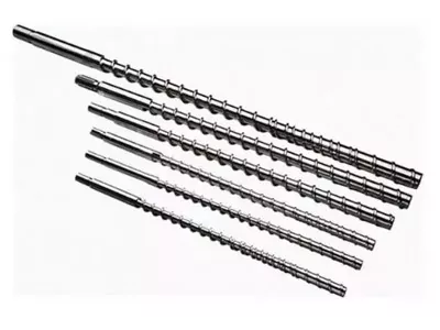
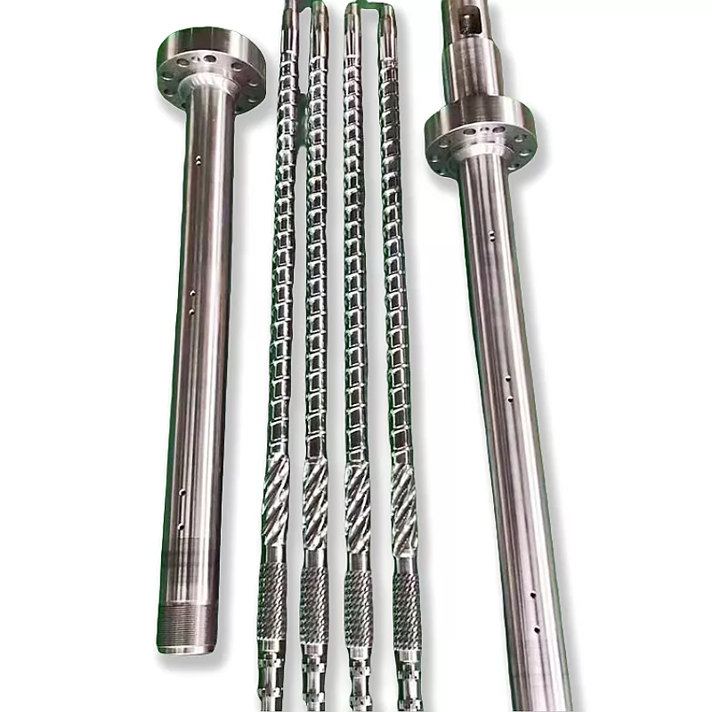
Our film range lists L/D options of 25:1, 28:1, 30:1, 33:1 and 35:1. Those choices provide length options, not a prescribed metering depth for every resin. A supplier still needs the actual channel profile and the operating requirement.
The transparent-granulation production details likewise describe a coordinated design approach. We would not turn a general material table into an absolute depth requirement for every transparent formulation. Ask for the proposed drawing and the reason for its depth choice.
When comparing extruder screws and barrels, the useful question is whether the proposed combination addresses your material and machine. A generic PE or PP label cannot settle that question.
Extruder screw wear issues or a channel-depth mismatch?
A gradual performance change and a limitation present from commissioning deserve different investigations. Neither proves the root cause by itself. Compare the original duty, current operating records and actual component condition before modifying the channel profile.
Separate root wear, flight-tip wear and barrel wear
| Change observed | Machined-depth relation Hs | Radial-clearance relation c |
|---|---|---|
| Root diameter decreases | Increases | Unchanged |
| Flight outside diameter decreases | Decreases | Increases |
| Barrel bore increases | Unchanged | Increases |
These are consequences of the dimension definitions, not a prediction that wear occurs at only one surface. Actual parts can have several changes together. Record corresponding stations and orientations; do not reduce an uneven wear pattern to a single average depth.
Our screw-and-barrel measurement guide explains the paired screw and bore records. Use the approved drawing as the design reference. A worn sample shows the remaining geometry, not necessarily the geometry that should be manufactured next.
Check upstream restrictions before deepening the channel
Ask whether material reaches the metering section in the intended condition and at the intended rate. A downstream pumping calculation cannot, by itself, prove that feeding and melting are adequate. The published film-line example below shows how an upstream restriction can create misleading downstream symptoms.
Do not treat every partly filled region as a fault. Deliberate starve feeding and vented sections have different design requirements from a region intended to operate filled and pressurized. State which arrangement you are evaluating before interpreting the measurements.
We would separate three decisions: restore a worn profile, change geometry for a revised duty, or correct another restriction. Ordering a different screw before making that distinction can leave the production problem unresolved.
What a published film-line project reveals about channel depth
Why we would check the barrier entry before changing metering depth
A film-line case documented by Mark A. Spalding in the SPE Extrusion Division technical paper shows why we would investigate the upstream restriction before changing metering depth.
The LDPE line used an 88.9 mm screw with a 33:1 L/D and a 5.8 mm metering-channel depth. It produced 148 kg/h at 91 rpm, with an extrudate temperature of 232°C. Intermittent gel and carbon contamination developed during operation.
Calculations and a polymer-solidification examination identified a restriction at the barrier-section entry. Parts of the downstream metering channel were only partially filled, and stagnant material degraded. The problem was not solved by simply providing more metering-channel volume.
After the barrier entry was modified, the line maintained 148 kg/h at about 69 rpm. Extrudate temperature fell to 223°C, and specific output increased from 1.63 to 2.14 kg/(h·rpm), approximately 30%. The paper reported no further gel showers after the modification.
Our conclusion from this project would be to verify what reaches the metering section before revising its depth. For a comparable film-screw inquiry, we would request the barrier-entry geometry and operating records alongside the channel dimensions. The useful result here was the same production rate at lower speed and temperature, not a 30% increase in hourly output.
The transferable lesson is the diagnostic sequence. The published 5.8 mm depth is part of that project's description, not a recommended depth for another machine or a Nanhaiya product specification.
What an extruder drawing must show before changing channel depth
How we would review a request for deeper screw channels
If a film line needs more output, we would not approve deeper screw channels from that requirement alone. Our first question would be whether the existing limitation is material intake, incomplete melting or pressure generation. Those problems can look similar at the discharge end but require different changes.
We would compare the approved drawing with measurements from the existing screw and matching barrel. Root diameter, flight outside diameter and barrel bore belong in separate columns. A worn barrel increases running clearance; it does not automatically increase the channel depth machined into the screw. Copying a worn assembly without identifying these differences can preserve the original problem.
Next, we would examine the operating records: resin grade, recycled content, screw speed, accepted output, melt temperature, pressure and drive load. A single maximum-output figure would not justify a geometry change. We need to understand the conditions under which the line loses quality or stops gaining useful output.
Our PE/PP high-speed screw design combines screw geometry with a special feed-slot barrel and a matched drive arrangement. We would review those features together. Increasing downstream channel volume cannot compensate for material that the feeding section cannot consistently deliver.
For transparent granulation, our published design combines longer L/D with lower rotational speeds, milder shear and smooth transitions. We would preserve that processing objective when reviewing channel depth, rather than select a deeper profile simply because it offers more space.
Before manufacture, we would mark every retained and revised dimension, check the drive and installation limits, and agree on production acceptance. The proposal must explain what the new channel profile changes and how that change will be judged. If the evidence points to feeding, wear or a downstream restriction, we would address that issue before recommending a different screw.

A six-step channel-depth review
- Define the incoming material and duty. Identify solid or melt feeding, resin grade, additives, product criteria and target accepted output.
- Confirm the current geometry. Supply flight and root diameters, depth references, zone lengths, lead, starts, flight width and matching barrel dimensions.
- Establish the operating baseline. Record speed, good output, pressure, measured melt temperature, drive load and material condition using consistent methods.
- Identify the limiting task. Compare feeding, melting, pumping and downstream constraints before selecting a revised profile.
- Check the complete assembly. Review wear, remaining root dimensions, working surfaces, drive limits, interfaces and installation requirements.
- Agree on acceptance. Specify dimensional inspection and production-comparison conditions, including product quality and the intended operating range.
The resulting proposal should distinguish a restoration of the original geometry from a redesign. Mark which dimensions remain unchanged and explain the processing purpose of each revision. That gives purchasing and production the same basis for approval.
Send the drawing with the production requirement
Zhoushan Nanhaiya Plastic Machinery Co., Ltd. provides custom screw design and manufacturing. Our technical service matches groove depth and other specifications to the material, equipment and required capacity.
Send the screw and barrel drawings, material details, wear records and operating data so we can review the proposed change.
Discuss your screw-and-barrel project
Email: info@nhyscrew.com
Phone: +86 135 0580 9643
Frequently asked questions about extruder screw channel depth
How do you calculate extruder screw channel depth?
For machined depth measured from the flight envelope, subtract root diameter from flight outside diameter and divide by two at the same section. If a flow model measures from the barrel wall, its channel height also includes radial clearance. Confirm the reference surfaces before comparing values.
Is channel depth the same as screw-to-barrel clearance?
No. Machined channel depth describes the screw profile between its root and flight envelope. Running clearance describes the gap between flight tips and the barrel. A larger barrel bore can increase clearance without changing the machined depth of the screw. Record both dimensions separately.
Does a deeper metering channel always increase output?
No. Depth influences both drag flow and pressure-driven flow. Under an opposing pressure gradient, part of the ideal delivery is offset. Material behavior, metering length, temperature and die resistance also matter. More geometric space is not proof of more output meeting the product requirements.
Can shallower channels increase melt temperature?
They can change shear and thermal conditions, but depth alone does not determine the final temperature. Compare actual melt measurements, output and drive load under defined conditions. A local shear-rate estimate or barrel setpoint cannot establish the complete temperature history of the material.
Is there one recommended channel depth for PE or PP?
No single value describes every PE or PP application. Specify feed state, resin grade, feeding arrangement, melting duty, discharge pressure and required output. Review a dimensioned profile with the matching barrel and drive. A depth quoted for a published case is not a universal material specification.
Can I machine an existing screw deeper to increase production?
Do not authorize that change from an output target alone. Check the remaining root section, working surface, complete geometry, matching barrel and drive requirements. First determine whether depth is actually limiting the process. Correcting feeding, wear or an upstream restriction may be the appropriate action instead.