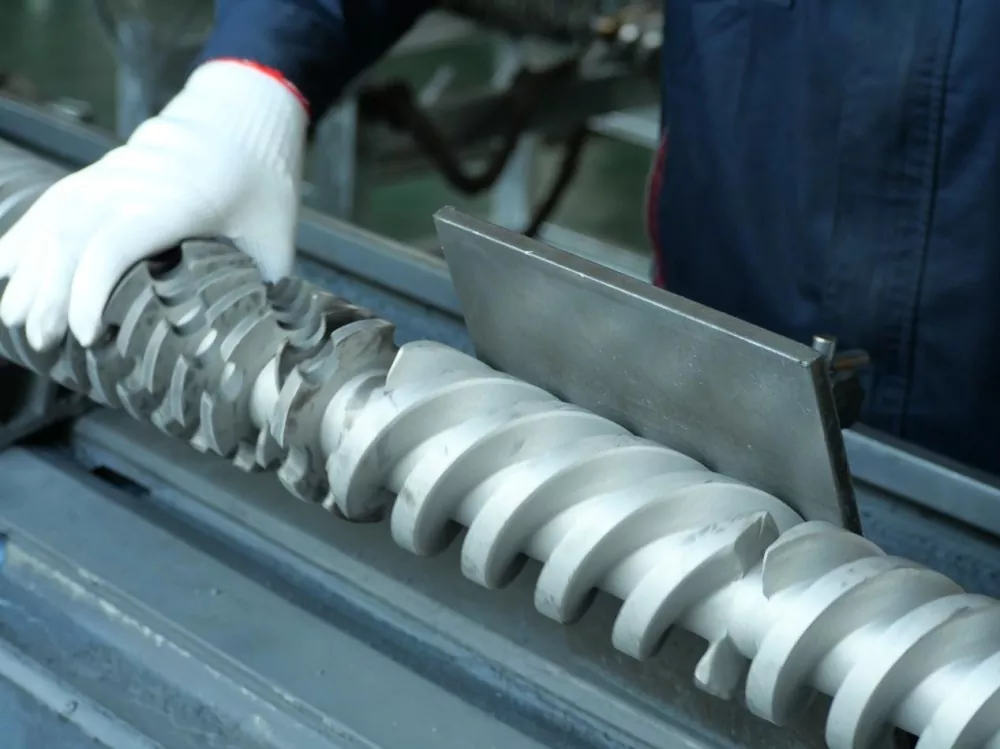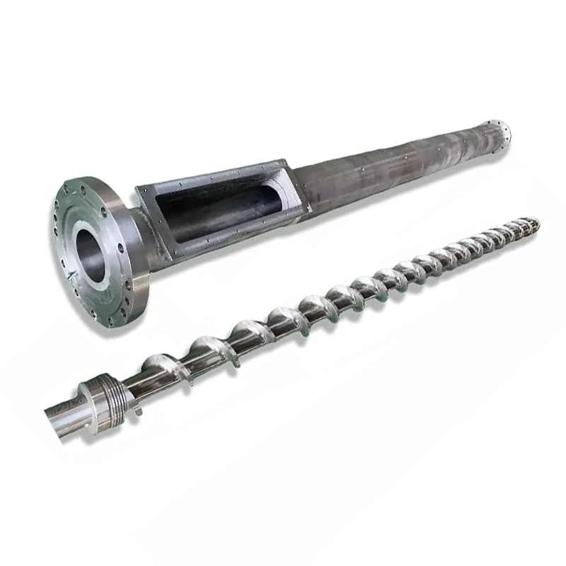

What are pitch, lead and starts on a plastic extruder screw?
A request for a "65 mm pitch screw" leaves important geometry unresolved. We need to know whether that dimension identifies adjacent-flight spacing or the advance of one helix, and whether the section has one start or several. A single-screw extruder can use a multi-start section: machine screw count and thread-start count describe different things.
| Term | Meaning here | Check |
|---|---|---|
| Pitch, P | Axial spacing between corresponding points on adjacent flights | Which flights are adjacent? |
| Lead, L | Axial advance of the same helix through 360° | Trace one identified helix |
| Starts, z | Number of independent helices in a regular section | Count starts, not visible turns |
When lead equals pitch
For regular, equally spaced helices with the same constant lead, L = z × P. A single-start section therefore has L = P. With two starts, adjacent-flight pitch is half the lead. Those statements describe geometry, not the distance a polymer particle travels per revolution.
Do not count a barrier section as two identical channels
A barrier flight separates solids and melt channels with different duties. Its additional flight does not automatically create the equally spaced, identical geometry used in the simple relationship above. Variable-lead regions also need local dimensions rather than one end-to-end pitch measurement.
Use a section drawing when discussing an extrusion screw. The SPE metering-channel analysis requires lead, starts, flight width, depth and section length as separate inputs. A pitch label alone cannot replace that information.
How do screw lead and diameter determine helix angle?
For the regular cylindrical helix used here, define θ relative to a plane perpendicular to the screw axis. Define Dref as the diameter of the reference cylinder on which that helix is evaluated. Then use the lead of that same helix:
θ = arctan[L / (π × Dref)]
Use consistent length units for L and Dref. Screw speed does not enter this geometric relationship. An angle measured relative to the axis is complementary to the angle defined here, so check the convention before comparing drawings or software outputs. Likewise, an outer-surface angle is not interchangeable with a root-surface angle.
A controlled three-way comparison
Assume Dref = 65 mm for all three hypothetical sections. The following values follow from the helix geometry; they are not Nanhaiya product specifications or measured production results.
| Section | Starts | Pitch P | Lead L | θ |
|---|---|---|---|---|
| A: single-start baseline | 1 | 65 mm | 65 mm | 17.66° |
| B: retain A's lead | 2 | 32.5 mm | 65 mm | 17.66° |
| C: retain A's pitch | 2 | 65 mm | 130 mm | 32.48° |
B adds a start without changing the reference helix angle. C changes both the lead and angle. Neither comparison proves higher output: flight width, usable channel area, depth and operating conditions remain unresolved. Penn State's extrusion notes distinguish helix geometry from the flow calculation that uses it.
Does a larger pitch always increase extruder output?
No. Increasing lead changes channel geometry and the direction of relative surface motion, but actual delivery also depends on the pressure gradient, melt viscosity and material supplied from upstream. A larger open-discharge estimate is not a promise of more accepted product through the existing die.
More than one geometric term changes
In a simple unwrapped, shallow-channel model, the down-channel surface-velocity component contains cos θ. Channel width also depends on lead, starts and flight width. Changing lead therefore changes more than the empty space visible between flights. Measure flight width perpendicular to the flight when that is the convention required by the calculation.
Jim Frankland's drag-flow evaluation distinguishes the full angle-dependent expression from a standard-pitch simplification. Do not retain a standard-geometry coefficient after changing the geometry that justified it. An inch-based coefficient also cannot be transferred unchanged to a millimetre calculation.
The pressure condition can reverse a simple conclusion
When pressure rises toward the outlet, the pressure-flow contribution opposes delivery from screw rotation. If the metering inlet is already pressurized, using discharge pressure alone can misrepresent the pressure increase across that section. Groove-fed arrangements and other upstream conditions can also invalidate a blanket claim that drag flow is an absolute output ceiling.
The Penn State screw-and-die model places the operating point at the intersection of their characteristics. Its Newtonian, isothermal treatment is a useful explanation, not a full prediction of pellet melting or a shear-thinning production melt. We would approve a lead revision only after checking the limiting section and required pressure duty.
Constant vs variable lead: how do pitch, depth and compression interact?
A constant-lead screw can still compress material through a changing channel depth. A variable-lead design adds another geometric change. Compare the profiles by section, rather than treating either label as a complete specification or as evidence that one design must perform better.
| Section | Review alongside lead | Avoid this shortcut |
|---|---|---|
| Feed | Particle form, bulk density, feed opening and barrel arrangement | Using a melt-flow calculation to predict solids intake |
| Transition | Depth profile, available melting length and material condition | Calling any reduced spacing an adequate melting design |
| Metering | Channel width and depth, viscosity, inlet and outlet pressure | Equating wider spacing with more delivery against the die |
| Vented stages | Stage balance and downstream pumping requirement | Ignoring the pressure needed after the vent |
Compression ratio needs its geometric conditions
The familiar depth-based extrusion screw compression ratio is useful for conventional comparable-flight geometry with the same lead in the sections being compared. If lead, starts or flight geometry changes, check the intended channel-volume definition. Two endpoint depths alone may no longer describe the comparison adequately.
Do not use decreasing lead as a substitute for confirming that material melts where the design expects it to melt. Nor should increasing lead automatically be described as gentler processing: residence, fill, mixing and temperature depend on the complete operating condition.
For a vented screw, the downstream stage must handle what arrives while meeting the outlet pressure requirement. The SPE troubleshooting paper explains how an unbalanced stage arrangement can cause vent flooding. That is a capacity-balance problem, not a reason to copy a twin-screw conveying-element sequence into a single-screw design.
Match screw lead to film, high-speed PE/PP and granulation
Our single-screw range serves different processing duties. We would start a pitch review with the application and present operating problem, then check whether the proposed geometry supports that duty. A polymer name alone leaves the grade, additives and feed condition unresolved.
Film: preserve the conditions behind accepted output
Our LDPE/HDPE film screw page describes configuration choices for different formulations and production requirements, including 25:1, 28:1, 30:1, 33:1 and 35:1 L/D options. Those lengths do not identify the pitch or lead. For a film proposal, we would request the actual profile and compare output alongside gauge and appearance requirements.
High-speed PE/PP: include the feed barrel and drive
Our PE/PP high-speed single-screw application combines screw-structure choices with a special feed-slot barrel and drive considerations. An extruder feed barrel is therefore part of the review, not an accessory to ignore. We would not attribute a combined system result to lead alone or assume that the existing drive can absorb a revised load.
Transparent granulation: evaluate the whole flow path
For transparent granulation, our application-specific production details describe longer L/D, lower rotational speed, milder shear and smooth transitions. That combination matters when judging a lead change. Nominal capacity is not a useful gain if black specks, colour change or unmelted material make more of the output unacceptable.
What should an extruder screw drawing show before a lead change?
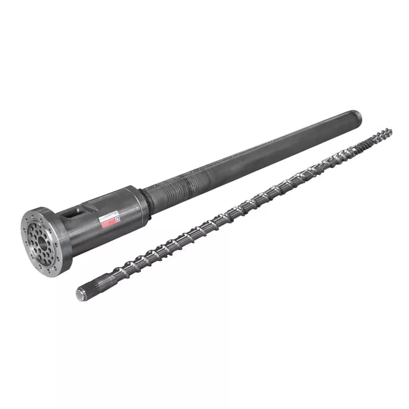
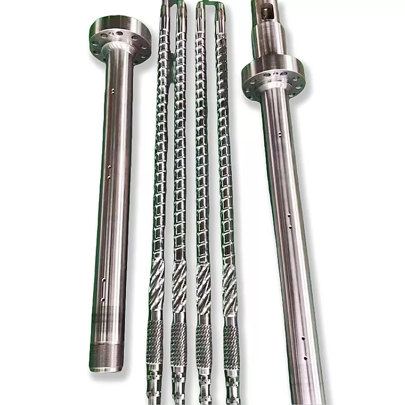
A useful extruder drawing identifies the feature, measuring direction and section. "Same as the sample, with a larger pitch" is not enough when the sample is worn, contains a barrier section or changes geometry along its length. We would first establish which dimensions still represent the intended design.
Trace one helix, then record local geometry
Physical inspection belongs on an isolated, cooled component under the plant's approved procedure, with suitable lifting support and qualified personnel. Identify a flight and follow it through a complete turn at the stated angular reference. Record its axial advance. Separately measure adjacent-flight spacing and establish the number of starts in that section.
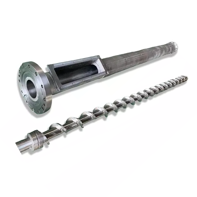
For variable lead, report local values and transition locations. Do not estimate a manufacturing dimension from a perspective photograph. Photos help identify features and damage, but they do not establish the measuring reference, inspection uncertainty or original unworn profile.
| Drawing information | Reason for including it |
|---|---|
| Diameter and reference surfaces | Define the angle and depth calculation |
| Lead, starts and handedness by section | Identify the actual helix arrangement |
| Depth, flight width and section lengths | Describe usable flow geometry |
| Barrier, mixing and vent features | Locate restrictions and changes in duty |
| Barrel bore and machine interfaces | Check the mating assembly and installation |
Keep design recovery separate from wear assessment. Our screw-and-barrel wear measurement guide explains why corresponding screw and bore measurements matter. A lead review cannot correct excessive clearance merely by changing flight spacing.
Pitch mismatch or extruder screw wear issues: what should you check first?
Look at when the problem appeared. A gradual loss on an unchanged duty calls for a different investigation from a failure that begins after changing resin, feed form or required output. Neither history proves the cause, but it tells us which evidence to request first.
Low output is a symptom, not a pitch measurement
Check whether the feed system supplies material consistently, whether melting is complete and whether the screen pack or die imposes a changed restriction. Record the screw speed, accepted output, actual melt temperature, pressure and drive load together. Barrel heater settings do not replace a melt-temperature measurement.
| Observation | Check before redesign | Decision supported |
|---|---|---|
| Output declines gradually | Material consistency, screw/barrel condition and restrictions | Restore condition or review the changed duty |
| Problem follows a formulation change | Feed behaviour, melting and required pressure | Assess whether the profile still matches the material |
| More rpm gives more heat but little accepted output | Limiting section, melt quality and downstream capacity | Investigate the bottleneck before increasing lead |
| Pressure fluctuates | Time-aligned feeding, temperature and pressure records | Separate instability from a steady pumping limitation |
The SPE analysis shows why an upstream restriction can leave part of a metering section unfilled. Altering the apparent downstream capacity would then miss the controlling problem.
We would retain a working profile when the evidence supports restoring material preparation or component condition. We would investigate redesign when a documented duty change or capacity mismatch remains. An expensive replacement is not automatically the appropriate response to an unexplained symptom.
What can a published lead-optimization project prove?
When I assess a lead revision, I first ask which limitation it addresses. Mark Spalding's published compounding-line project concerns a 15-inch melt-fed single screw downstream of a compounder. Its original channel was too deep for the pressure duty, and discharge temperature limited operation because of a flame-retardant additive's degradation risk.
| Item | Original operation/design | Revised design |
|---|---|---|
| Metering depth | 1.73 in. | 1.18 in. |
| Lead / diameter | 1.0 | 1.2 |
| Rate and screw speed | 3,280 lb/h at 15 rpm, reported operation | 8,500 lb/h at 15.5 rpm, simulated |
| Revised discharge temperature | Not a matched value in this comparison | 174°C, simulated |
Spalding reports an 18% increase in the specific rotational rate from the lead change. That describes the rotational contribution per rpm, not an 18% measured increase in whole-line output. The new design also requires additional drive torque.
I would not assign the entire predicted improvement to lead: depth changed too, and the article's simulations use stated pressure conditions. The revised rate and temperature are predictions, not a reported commissioning acceptance test. This distinction matters when comparing proposals from different suppliers.
The useful design lesson is to consider a lead increase alongside pressure duty and channel depth, rather than repeatedly deepening a channel to chase capacity. This is a melt-fed case, not a pellet-plasticating trial. Its dimensions cannot become a universal recipe for film, pipe or transparent granulation.
Reviewing the screw and barrel before approving a lead change
Our factory review starts with the problem
When I receive a request to increase pitch because a screw cannot deliver enough output, I would separate the questions before revising the drawing. First, does the customer mean adjacent pitch or the lead of one helix through a full turn? I would then check starts, depths and section lengths. Measuring only neighbouring flights can misidentify a multi-start section.
For our PE/PP high-speed single-screw application, I would review the screw, feed-slot barrel and drive together. If feeding cannot keep up, melting is limited or screen resistance has increased, changing lead alone may not solve the problem. Once the limiting duty is understood, I would list proposed lead, width and depth changes separately and check their match to the metering requirement.
During a comparison, I would hold the resin, formulation and downstream configuration constant and record accepted output, rpm, melt temperature, pressure fluctuation and load together. My criterion is stable production at the required quality, rather than the size of the pitch increase.
A five-step review and validation workflow
- Define the duty. Provide the resin grade, additives, recycled content, feed form, product requirements and target accepted-output rate. Describe what changed and when the problem appeared.
- Establish the geometry and machine condition. Supply the screw profile, matching barrel measurements, interfaces and drive details. Identify lead, starts, depth and section lengths rather than relying on a photograph.
- Record a comparable baseline. Capture stable operating conditions and time-aligned output, rpm, measured melt temperature, pressure, load and defect criteria. State the pressure and temperature measuring locations.
- Approve a dimensioned change matrix. Mark retained and modified dimensions, the reason for each change, material and surface requirements, and the agreed dimensional inspection method. Check drive capacity and assembly compatibility.
- Validate under agreed conditions. After installation and commissioning under the machine procedure, compare the same material and downstream configuration. Judge accepted output and quality together, then document the operating window supported by the trial.
Specific output, such as kg/(h·rpm), helps compare delivery per revolution. It is not energy efficiency: that needs a defined energy measurement and an accepted-mass basis. Keep dimensional acceptance, processing performance and product-quality acceptance as separate checks.
Our technical matching service considers the production material, equipment model and capacity requirement alongside dimensions and material selection. Send that information before choosing a revised lead.
Discuss your screw profile with Nanhaiya
Send your drawing, material details and current operating records to Zhoushan Nanhaiya Plastic Machinery Co., Ltd. We can review the relevant single-screw application and parameter-matching requirements with you.
Request a screw specification review
Email: info@nhyscrew.com
Phone: +86-13505809643
FAQs about extruder screw pitch and lead
Is screw pitch the same as screw lead?
They are equal for a regular single-start section. On an equally spaced multi-start section with a common lead, lead equals adjacent-flight pitch multiplied by the number of starts. Trace the same helix through a complete turn before comparing dimensions. A barrier or variable-lead section needs its own drawing interpretation.
Does a double-start screw have twice the output?
No. Adding a start at the same lead changes adjacent spacing and divides the available channels; retaining the same adjacent pitch instead changes the lead. Neither operation establishes output without the depth, flight width, material, feeding and pressure conditions. State which dimensions remain constant before comparing two designs.
Why is approximately 17.7° common in square-lead examples?
With the angle measured from a transverse plane and lead equal to the stated reference diameter, arctan(1/π) gives approximately 17.66°. That is a geometric result, not a universal best processing angle. A different diameter reference or an angle measured from the axis changes the number being compared.
Can pitch be changed without changing channel depth?
A design can change lead or adjacent spacing while retaining a specified depth, but the channel geometry will not remain otherwise identical. Review starts, usable width, flight geometry and section duty together. If feed and metering leads differ, check the intended channel-volume compression definition rather than relying only on a depth ratio.
Can a photograph identify the correct replacement screw?
A photograph can help identify visible features, but it cannot establish a complete replacement specification. Perspective, hidden surfaces and wear leave dimensions unresolved. Use an approved drawing or a controlled inspection of the screw and matched barrel, together with machine interfaces, material details and the required production duty.
What information is needed before increasing screw lead?
Provide the current section geometry, resin grade and formulation, feed arrangement, machine and drive details, and downstream configuration. Include accepted output, rpm, measured melt temperature, pressure and load records with the defect criterion. The review should identify the limiting duty and agree how a revised design will be compared before manufacture.