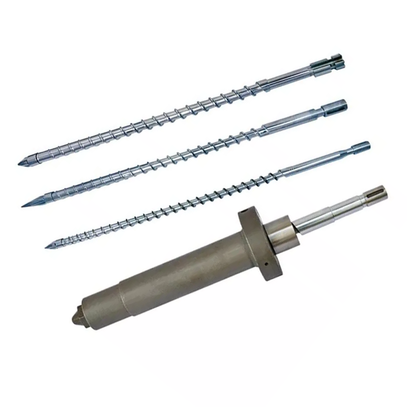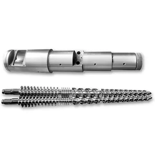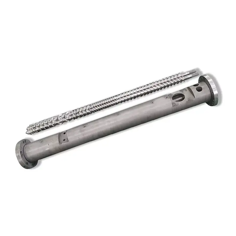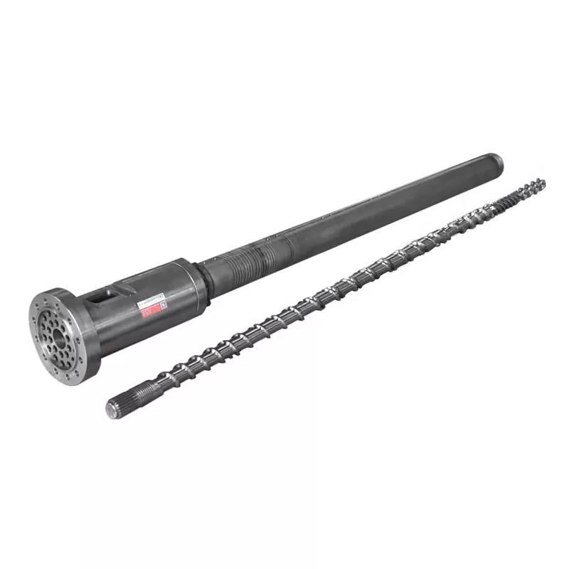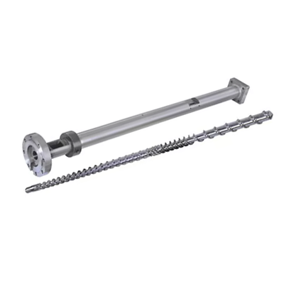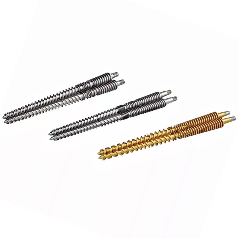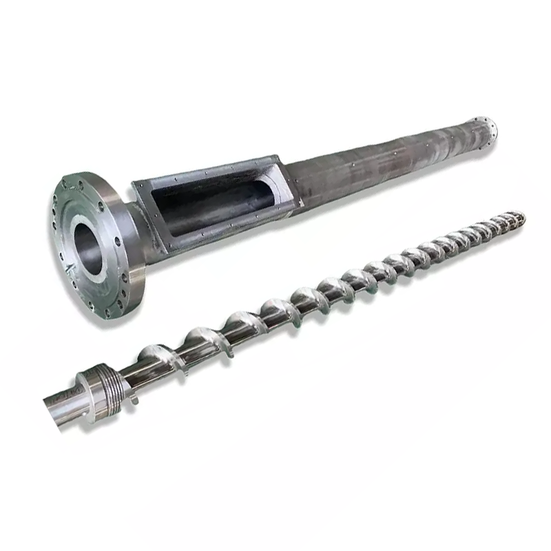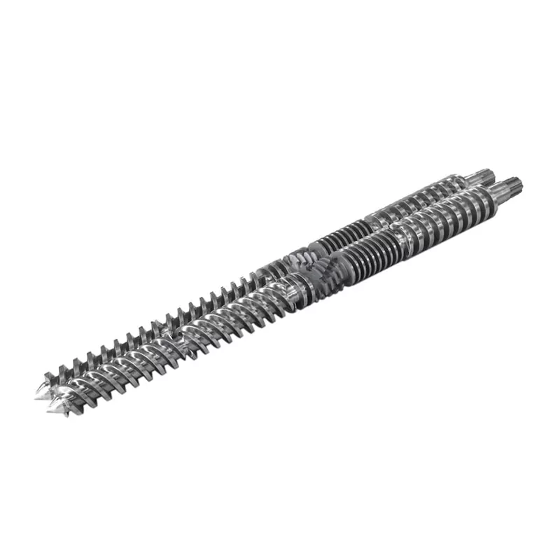

Replace a single extruder screw when measured wear or damage prevents the existing design from doing its job. Upgrade it when the screw is mechanically sound—or is due for replacement—but a documented change in resin, product quality or output demands a different melting, mixing, venting or wear-resistance strategy. Before either decision, check the barrel and the rest of the line: a new screw cannot repair a poor feed, wet resin or a restricted die.
- Establish a baseline for output, screw speed, melt temperature, head pressure, motor load and the finished-product defect.
- Separate process and downstream faults from screw or barrel wear before approving a purchase.
- Choose among continued use, an equivalent replacement, a geometry change and a different working-surface system.
- Check the proposed design against the barrel bore, drive interface, available power, vent hardware and die resistance.
- Agree on a drawing, inspection record and controlled production trial rather than a promised percentage improvement.
First, find the constraint—not just the symptom
A drop in output makes a worn screw an obvious suspect, but it is not a diagnosis. Feeding can change with pellet geometry or recycled content; a screen pack can accumulate resistance; a temperature sensor can drift; and a die can alter the pressure the screw must work against. If the process used to run the same resin, product and output, record what changed before specifying new metal. Nanhaiya's surging diagnostic guide follows this sequence from feed and process checks to mechanical inspection.
Compare the current line with a documented healthy period at the same resin grade, formulation, die and screen configuration. Write down screw speed, throughput, head pressure, melt temperature measured at a defined location, motor current or torque, and the defect rate or finished-product measurement that matters to the buyer.
Note whether the trouble appeared suddenly after a material change or gradually over operating time. These patterns do not prove a cause, but they tell you what to test next. A repeatable fall in output at the same speed and conditions supports a different investigation from occasional pressure spikes after a feed change.
| Observed symptom | Check before blaming the screw | When screw inspection becomes useful |
|---|---|---|
| Lower output at the same speed | Feed rate, screen and die resistance, resin change, motor load | Persistent loss after process variables are restored; compare screw and barrel wear maps |
| Unmelted particles or gels | Actual melt temperature, throughput demand, contamination and residence time | Melting capacity is still inadequate under a controlled, repeatable trial |
| Color streaking | Masterbatch preparation, dosing and material changeover | Distribution remains poor after feed and cleaning checks |
| Bubbles or discoloration | Drying, contamination, trapped volatiles and thermal history | Material preparation is controlled but the screw's venting or residence-time arrangement remains unsuitable |
When physical inspection is justified, measure the screw and barrel as a pair rather than treating one outside diameter as the whole wear story. Nanhaiya's wear-measurement procedure describes station-by-station screw diameter and barrel-bore checks. A worn sample tells you its present condition, not automatically its original design. That distinction prevents a factory from faithfully copying damage into a replacement.
Keep, replace or redesign: four different purchasing decisions
“New screw” is not a complete purchase specification. A buyer who has located the fault still has to decide what the next part should preserve and what it should change. If the screw and barrel measure within the accepted design limits and the production problem disappears after a feed or temperature correction, continued use may be the best decision. Spending money on a new profile in that situation can introduce a different melt-temperature or pressure problem without solving the original one.
An equivalent replacement makes sense when the line previously performed well, the application has not changed and the current screw is worn, bent or damaged. In that case the objective is to recover the approved geometry and machine interfaces—not the dimensions of an eroded sample.
A geometry upgrade is different: the current duty now asks for more complete melting, another kind of mixing, a changed formulation or a new output target. A surface-system upgrade addresses abrasive or corrosive duty, not a melting problem by itself. Some projects need both geometry and surface changes, but the reasons should remain separate on the approval drawing.
| Decision | Evidence that supports it | What the order must define |
|---|---|---|
| Keep the current screw | Measured condition is acceptable; a non-screw cause explains the defect | Process correction, monitoring interval and retained baseline |
| Equivalent replacement | Original duty is unchanged; documented wear or damage has reduced performance | Approved original geometry, interfaces, material, surface and inspection points |
| Geometry redesign | Changed material or production target exposes a measured melting, mixing or venting limit | Exact design changes, machine constraints and controlled acceptance trial |
| Working-surface upgrade | Wear map and formulation identify an abrasion or corrosion mechanism | Substrate, treatment or alloy location, mating barrel condition and verification method |
Do not let a quote merge these four paths into a vague “high-performance” part. Request a marked comparison between the existing approved drawing and the proposed revision. Nanhaiya's replacement specification guide begins once a replacement route is chosen and details the dimensions and documents an RFQ should contain. This article answers the earlier question: whether replacement is justified and whether a copy is still the right design.
Choose the design change from the product defect
Our aluminum-plastic panel single screw combines a barrier-type mixing section, polished flow channels and a smoothly shaped head. These features address different tasks: melting the feed, distributing colorants and flame retardants, and reducing places where polymer can remain and degrade.
For uneven core color, we would review additive preparation and the mixing section together. For recurring black specks, we would inspect channel condition, head transitions and the downstream flow path. A harder surface alone would leave a mixing or retention problem unresolved. The defect tells us which drawing features deserve attention.
The panel-screw details identify common diameters of 65, 90, 120 and 150 mm, selected according to panel width and production demand. A replacement drawing also needs the head shape, mixing arrangement and polished surfaces. Otherwise, a dimensionally compatible part may omit the feature the process needs.
A barrier section deserves review when incomplete melting remains at the required production rate. University of Minho-led research on conventional and barrier screw optimization found different outcomes for the studied LDPE and PP cases. That supports choosing the geometry with the resin and process objective, rather than treating every barrier design as an automatic upgrade.
A vented conversion requires its own review of the barrel vent, pressure profile, vacuum equipment and downstream pumping section. If the duty has changed to incorporating several ingredients on the line, examine the whole architecture through our single- versus twin-screw pelletizing comparison. Changing one screw profile cannot supply missing line equipment.
Match the replacement to film, transparent resin or abrasive feed
Film production
Our LDPE/HDPE film screw range lists diameters from 30 to 150 mm and L/D options of 25:1, 28:1, 30:1, 33:1 and 35:1. It covers LDPE, LLDPE, HDPE, PP and PVC applications, including packaging and agricultural films. Bimetallic forced-feeding construction and tungsten-alloy treatment are among its options.
For a film replacement, tell us whether the objective is gauge stability, transparency, strength or recovery of lost output. Include the resin blend and existing L/D. We would preserve the feed behavior and melt delivery the die needs, then change the feature responsible for the measured limitation.
Transparent granulation
Our transparent-granulation screw has smooth head transitions, continuous grooves and threads, and surface treatments intended to reduce adhesion during material changes. Its application-specific production details describe a compression ratio of 2.0:1–2.5:1, a longer L/D and lower-speed processing with milder shear.
For this duty, review discoloration, black specks and cleaning behavior alongside output. The 2.0:1–2.5:1 ratio belongs to the transparent-material design described on that page. The drawing for a different material needs its own channel geometry and plasticization review.
Filled and recycled material
Our wear-resistant single screw range covers glass-fiber plastics, calcium-carbonate- and talc-filled compounds, recycled feed and corrosive plastics. Its construction options include nitriding, PTA reinforcement on flight tops and sides, and tungsten-carbide or nickel-based surface systems. Match the treatment location to the actual wear map.
Send material-test conditions with the recipe. ISO 1133-1:2022 defines MFR and MVR at specified temperature and load, and notes that the test shear rates differ from normal processing. The result helps identify the feed; the production trial establishes how the replacement handles it.
Check the machine before approving a stronger screw
Our film screw range includes 25:1 and 35:1 L/D options. For an illustrative 65 mm screw, if L/D uses working length, these correspond to 65 × 25 = 1,625 mm and 65 × 35 = 2,275 mm. The 650 mm difference shows why a longer profile requires a barrel and machine-envelope check.
Confirm how the approved drawing defines working length; drive-end and tip dimensions may be additional. Then check the feed-throat position, discharge interface, barrel bore and drive connection. Measure screw outside diameter and matching bore at named axial stations. That record determines whether the new screw can work with the existing barrel.
Then review the machine's working limits. Available screw length constrains where a barrier, mixer or vent stage can be placed. Motor and gearbox capacity limit what can be driven at the intended speed and pressure. The screen pack and die determine downstream resistance, so a screw that looks acceptable in isolation may run at a different pressure or motor load once installed.
Compression ratio, pitch, channel depth and clearance are not interchangeable headline specifications: each influences the balance of feeding, melting, pumping and thermal history. Ask the supplier to identify which measurements come from an original drawing, which come from the worn sample and which are proposed design changes. Do not transfer a dimension from one source to another without labeling it.
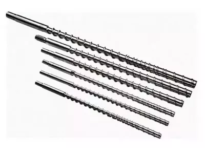
For precision fit, the accepted drawing should identify units, datums, tolerances, surface requirements and inspection locations. A polymer test can help characterize the feed, but it cannot establish mechanical fit. Conversely, a perfect diameter report cannot establish that the profile melts the customer's formulation properly. Both kinds of evidence belong in an upgrade review, and both must be associated with the actual part and machine. Nanhaiya's wear-mapping article gives buyers a more detailed method for the dimensional half of that job.
Turn our material specifications into an upgrade requirement
A wear-resistant quotation should identify the base steel, surface process, treated location and inspection requirement. Our product details offer several construction routes. Put the selected route into the RFQ so purchasing compares the same scope of supply, rather than grouping every hardened part under “bimetallic screw.”
| Construction | Our product specification | Order requirement |
|---|---|---|
| Wear-resistant screw substrate | 38CrMoAlA, SACM645 or 42CrMo steel options | Selected grade and heat-treatment route |
| Ion-nitrided screw surface | Hardness up to HV1000–1200 | Process, inspection locations and acceptance values |
| Local flight reinforcement | PTA welding on flight tops and side surfaces | Reinforced areas, finished dimensions and mating clearance |
| Wear-resistant barrel alloy | Alloy hardness exceeding HRC60 | Liner construction and inspection requirement |
| Extruder screw-and-barrel alloy option | Nickel-based/tungsten alloy; 2–3 mm depth; HRC58–65 | Component, alloy location, selected depth and hardness |
Construction sources: our Super Wear-Resistant Single Screw and Extruder Single Screw Barrel details. These rows concern different components and treatment routes; select the applicable construction on the project drawing.
For glass-fiber or mineral-filled feed, we would use the existing wear map to decide where reinforcement should act. Flight-top loss makes local reinforcement worth examining. Barrel scoring or an enlarged bore requires attention to the mating surface as well. A harder screw cannot restore a clearance that is already too large.
Keep hardness scales attached to their processes. The HV values above concern the ion-nitrided surface; the HRC values concern alloy constructions. Request the relevant test record for each. Record the geometry after surface processing as well, because the finished part must satisfy both the material requirement and the dimensional drawing.
For cost comparison, separate a new profile, surface reinforcement and a matching barrel into identifiable items. Attach the production problem each addresses: incomplete melting, retained material, flight wear or bore condition. That makes an upgrade decision specific enough for engineering approval and purchasing review.
Our factory review connects the defect to the drawing
We would start a film-screw review with the resin blend, film specification and last stable production record. Our film range offers several diameters and L/D choices, so the nominal diameter leaves important decisions open. Identify which original features must be preserved and whether the change concerns feeding, melting, mixing or wear.
For a panel-core project, we would put the mixing section, polished channel and head transition on the same review sheet. Those are the features described in our panel screw design. If color variation is the main defect, a proposal focused only on surface hardness misses the process objective.
For abrasive feed, we would mark the wear on the drawing and discuss PTA, nitriding or alloy options against that map. Our pre-sales service includes requirement diagnosis and matching diameter, L/D, groove depth and material. The review should finish with a defined part, manufacturing route and acceptance plan.
- Record the reference duty. Identify resin, additives, product, operating range and the defect that starts the project.
- Inspect the pair. Map the screw and barrel, including coating loss, scoring, corrosion and previous repairs.
- Select the product route. Relate the duty to film, panel, transparent-granulation or wear-resistant construction.
- Approve the changes. Mark revised geometry, steel grade, surface process and inspection points on the drawing.
- Agree on acceptance. Check the finished part and compare the installed process with the recorded baseline.
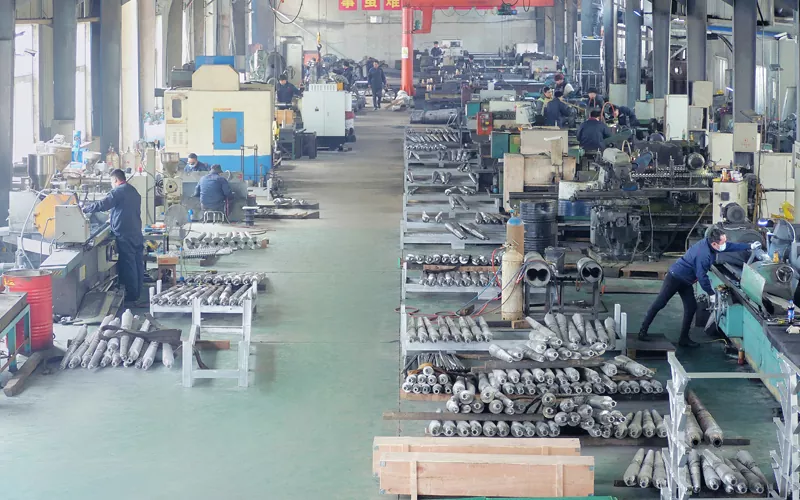
Our machining equipment includes CNC lathes for workpieces up to 6 m and five-axis centers for irregular flights and special flange structures. Bring the critical geometry into the drawing review so the production and inspection routes address the same features.
Judge the result against the original problem
An upgrade has worked only if it solves the buyer's stated constraint without creating an unacceptable new one. Suppose the aim is fewer unmelted particles at a specified output. The acceptance trial should record the material lot, output, screw speed, melt temperature, pressure, motor load and agreed particle-inspection method before and after the change.
If color uniformity is the aim, define a repeatable sampling point and quality criterion. If wear is the aim, a single start-up shift cannot prove longer service life; it can only establish initial fit and process behavior. A later inspection schedule must be agreed before claiming an endurance benefit.
Compare like with like. A higher output obtained after changing the resin, screen mesh, die or temperature settings is not proof that the screw alone caused the gain. Conversely, a redesigned screw should not be rejected because it was tested against a different product or a more restrictive downstream arrangement than the one used for the baseline.
Record these conditions beside the results rather than reducing the project to one attractive number. A useful acceptance report includes the drawing revision, component inspection results, installed barrel condition, trial conditions and observations about quality and stability.
The economic decision also needs a time horizon. An equivalent screw may carry the lower design risk if the original process is still correct. A more involved geometry can make sense if a measured melting or mixing limit causes recurring scrap or keeps the line below its required rate. A different surface may be justified by repeated, documented abrasion.
Ask for the extra purchase and qualification cost alongside the evidence for the expected operational benefit. No general percentage saving applies to every resin, line or duty. The replacement RFQ checklist helps translate that decision into a manufacturable order once the route is settled.
Bring Nanhaiya a production problem, not just a part number
At Zhoushan Nanhaiya Plastic Machinery Co., Ltd., we manufacture single screws, parallel twin screws and conical twin-screw barrels, with custom design and alloy spray-welding capabilities. Our single-screw applications include film, panel cores, transparent granulation and wear-intensive feed.
For an initial review, send the machine maker and model, nameplate and drive-end photographs, the original drawing if available, screw and barrel measurements, resin grade and formulation, normal output and speed, pressure and motor-load records, defect photographs and what has already been ruled out. State whether the request is for an equivalent part or an improvement to a defined production problem.
If the existing barrel is worn, say so at the start: it changes what a new screw can realistically accomplish. The detailed replacement guide lists the dimensions and documents needed for the next stage.
Nanhaiya can be reached through its published contact page or at info@nhyscrew.com. The company is based in Zhoushan, Zhejiang, China.
Discuss a single screw replacement or upgrade
Send your machine details, material, current line data and the problem you need the next screw to solve. Nanhaiya can review the information and identify what must be confirmed before a drawing or quotation is approved.
Send a technical inquiryEmail: info@nhyscrew.com · Product range: Nanhaiya Single Screws
Frequently asked questions
Can I fit a barrier screw in my existing barrel?
Possibly, but do not approve the retrofit from screw diameter alone. Check available working length, barrel-bore condition, drive and motor limits, die resistance and the resin's melting behavior. Define the expected benefit and a controlled trial before ordering a new profile.
Should I replace the barrel when I replace the screw?
Not automatically. Measure the barrel bore and screw outside diameter at matched locations, then compare the resulting clearance and wear pattern with the approved design. A worn or oval barrel can undermine a new screw, while a sound barrel may remain serviceable. See Nanhaiya's wear-measurement guide.
Will a new single extruder screw fix unstable output?
Only if the screw or its fit is the cause. Feeding, temperature control, screens, die resistance, material variation and barrel wear can also contribute. Establish a baseline, check those causes and inspect the parts before choosing an equivalent replacement or redesign.
When is an exact copy safer than a redesign?
Choose an equivalent replacement when the original screw delivered the required product with the same material and line, and documented wear or damage explains the current decline. Copy the approved design, not the worn profile. A redesign needs a separate, stated process objective and acceptance trial.
What should I send for a single screw upgrade review?
Send the machine model, original drawing or identified sample, drive-end and barrel dimensions, resin and additives, target product, current output, speed, temperature, pressure and motor load, defect photos, wear records and the outcome you need. Identify which values are measured and which are estimates.