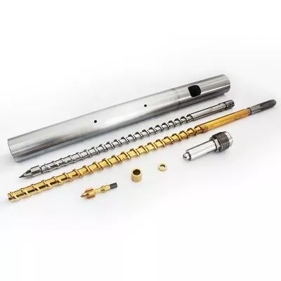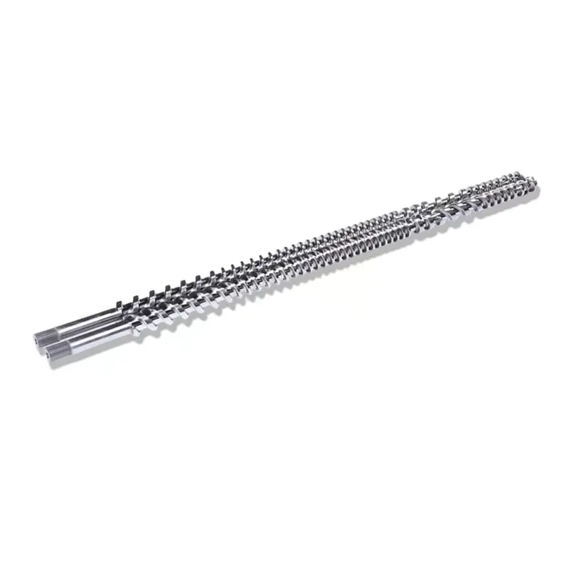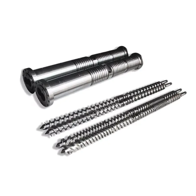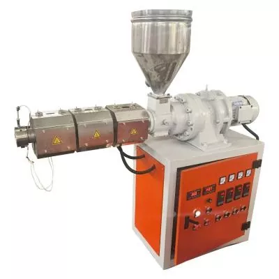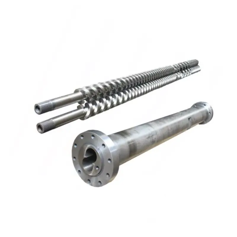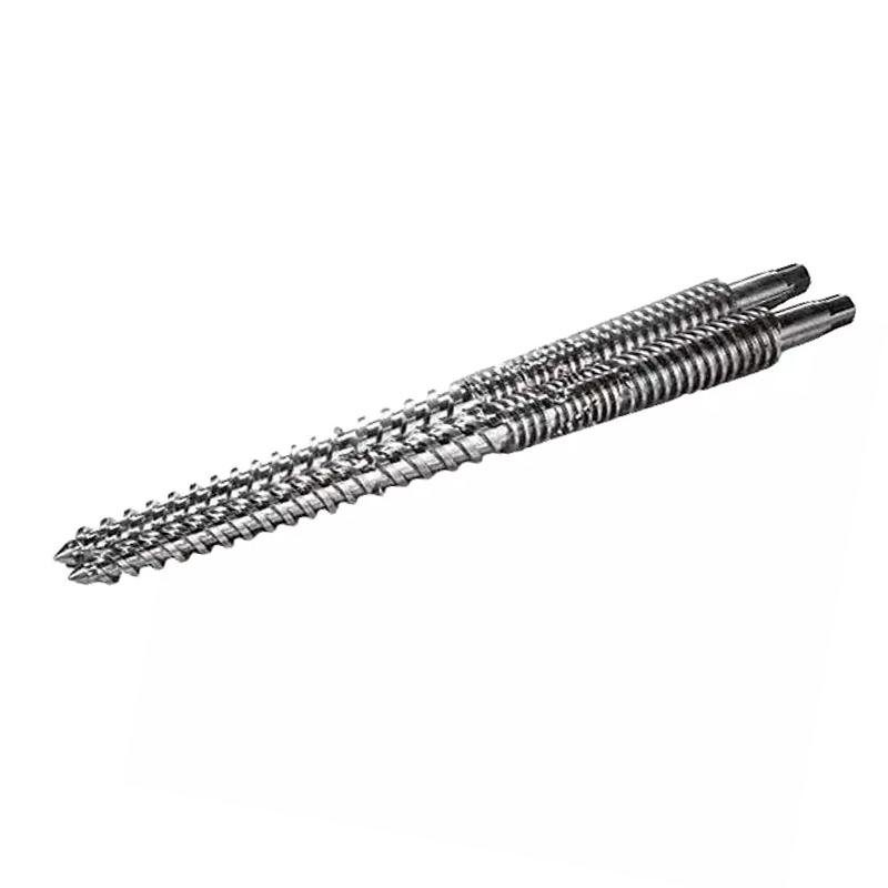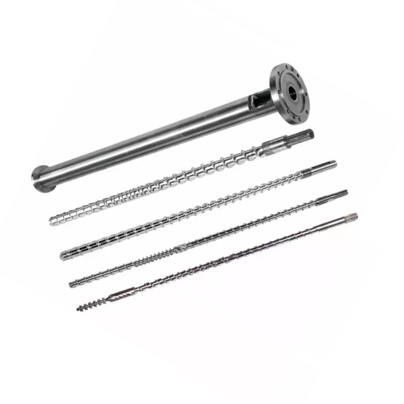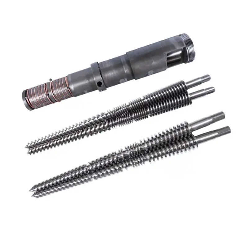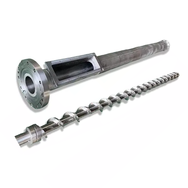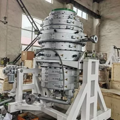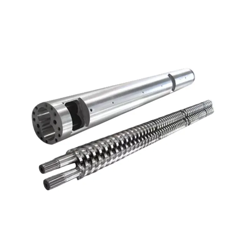

A replacement screw should match more than the machine nameplate. It must fit the mechanical interfaces, work with the actual barrel bore and suit the polymer, additives and production duty. This guide shows what a factory needs before it can review the part responsibly.
Quick Answer
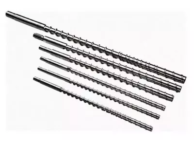
To specify a replacement single screw, send four groups of information: machine and interface details, a controlled dimensional record, the processed material and operating duty, and clear acceptance requirements. A worn sample helps, but it is evidence of both the original design and subsequent damage. The factory must distinguish between the two before approving a drawing.
Why the Extruder Model Is Not Enough
A machine model narrows the search, but it does not prove the installed screw revision. A production line may have been rebuilt, re-barreled or adapted to another resin. Two machines with the same nameplate can therefore use different working lengths, drive ends, feed relationships or flight geometry.
Begin with the manufacturer, model, serial reference and nameplate photo. Then verify the physical part. If the original drawing is available, identify its revision and compare it with the removed screw rather than assuming the drawing still matches the machine.
Buyers who are still choosing the basic screw type should first use Nanhaiya’s single screw barrel selection guide. This page begins one step later: the machine needs a replacement, and the job now requires a manufacturing definition.
Decide Whether to Reproduce or Revise the Existing Screw
A replacement project can follow two different paths. The first is functional reproduction: restore the intended geometry and interfaces without changing the process design. The second is an application-led revision: retain the machine interfaces but change selected geometry or surface protection to address a documented problem.
| Project path | Use it when | Evidence needed | Main risk |
|---|---|---|---|
| Reproduce the intended design | The line previously ran well and the replacement is routine. | Approved drawing, reliable unworn dimensions, machine interfaces and barrel condition. | Copying wear or an undocumented repair into the new part. |
| Revise the working design | The line has persistent melting, stability, wear or material-handling problems. | Process history, resin formulation, defect evidence, operating data and a clear design objective. | Changing geometry before ruling out settings, feed, barrel, die or maintenance causes. |
Do not request an “optimized” screw without defining what must improve and what must remain unchanged. Output, melt quality, temperature control, cleaning behavior and wear resistance can pull the design in different directions. A useful revision brief identifies the priority and the operating limits.
Build One Controlled Reference Package
Scattered photos, handwritten dimensions and an old PDF can contradict one another. Put the evidence into one controlled package and state which file governs the order. The factory should not have to guess whether a dimension came from the original design, the worn sample or a previous quotation.
Machine identity
Nameplate photo, manufacturer, model, serial reference and any rebuild history.
Drawing record
Drawing number, revision, units, datums, tolerances and the source of every added measurement.
Sample record
Full-length photos, close-ups of interfaces and wear, and labels that match the measurement sheet.
Operating record
Material formulation, output target, speed range, temperatures, pressure limits and failure history.
Photograph a scale or identified reference next to small features when practical, but do not use a photograph as a substitute for a controlled measurement. Perspective and lens distortion make screenshots unreliable for final dimensions.
Record the Dimensions That Control Fit and Function
A complete replacement drawing separates installation interfaces from working geometry. Interface errors can prevent assembly. Geometry errors may allow assembly but produce poor conveying, melting or pressure stability.
| Feature group | What to document | Why it matters |
|---|---|---|
| Overall and effective lengths | Overall length, working length and the axial location of each functional transition. | Controls installation, feed alignment and the position of the screw tip relative to the barrel and die connection. |
| Outside-diameter profile | Flight outside diameter at agreed stations along the screw, not one isolated reading. | Shows taper, localized wear and the relationship with the barrel bore. |
| Flight geometry | Pitch, lead, flight width, helix direction, number of starts and any barrier or mixing features. | Defines conveying and working geometry; these features cannot be recovered reliably from the outside diameter alone. |
| Root and channel | Root diameter or channel depth at defined axial locations. | Helps distinguish feed, transition and metering geometry and reveals where wear has altered the channel. |
| Drive end | Spline, key, thread, coupling, shoulder, seal and bearing-related dimensions. | Determines mechanical fit and torque transfer. |
| Tip and head | Thread, seat, nose geometry, mixing head or other end feature. | Controls assembly with the downstream component and affects dead space or material flow. |
| Barrel relationship | Bore measurements at agreed axial and circumferential positions plus feed-throat location. | Provides the mating condition needed to evaluate working clearance and alignment. |
Measurement quality is part of the specification
Record the instrument, method, measurement location and units with the result. NIST dimensional-metrology guidance notes that temperature, instrument geometry, alignment and other factors can contribute to measurement uncertainty. A long worn component should therefore not be reduced to a list of unexplained numbers from one handheld tool.
Technical reference: NIST dimensional laboratory criteria.
A Worn Sample Is Evidence, Not a Master
Wear is rarely uniform. Flight tips may lose material faster near one zone, corrosion may create local pits, and a long screw may bend or show runout. Previous hardfacing or grinding can also change the profile. Copying every measured value can reproduce the failure rather than the original geometry.
Map the screw by axial station. At each station, record multiple readings around the circumference when the method allows. Mark visible scoring, rounded flight edges, repaired areas and surface loss on a photo or sketch. The purpose is to show the pattern, not to generate false precision.
Do not calculate final clearance from the screw alone
The screw and barrel wear as a functional pair. A new screw installed in a heavily worn or out-of-round barrel may not restore the intended relationship. Measure the barrel bore and agree how the manufacturer will use those values before approving a one-part replacement.
If the reason for replacement is uncertain, compare the observed pattern with Nanhaiya’s article on premature wear on single screw surfaces. Keep diagnosis separate from the drawing: the first explains what failed; the second defines what will be manufactured.
Add the Material and Production Data the Drawing Cannot Show
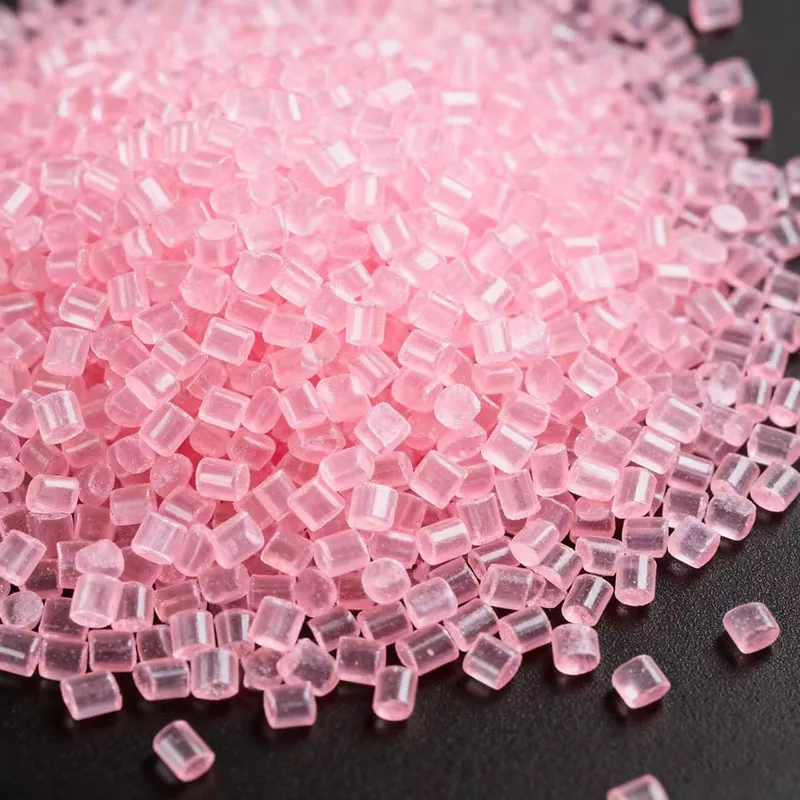
A mechanically accurate replacement can still be unsuitable if the application has changed. Resin behavior, filler, recycled content, additives, bulk density and moisture influence feeding, melting, mixing and wear. State the actual formulation range rather than naming only the base polymer.
Also include the target product and operating duty: expected output, normal and maximum screw speed, barrel temperature profile, head pressure or limit where recorded, venting arrangement, screen pack, die type and continuous or intermittent operating pattern. These details help the factory decide whether a reproduction is reasonable or a design review is needed.
A reference description of an extruder screw explains that channel volume commonly decreases from the feed end toward the pumping end to support feeding, compression, melting and pressure development. That relationship is why a supplier needs application data before changing channel depth, lead or zone layout.
Technical reference: Springer’s Encyclopedic Dictionary of Polymers entry on extruder screws.
Specify the Base Material and Working-Surface System Together
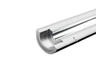
The base material supports mechanical loading. The working surface faces abrasion, corrosion, sliding contact and thermal cycling. A replacement RFQ should describe the service condition and the required evidence instead of asking only for “hard steel.”
For example, nitriding is a thermochemical treatment that diffuses nitrogen into a compatible steel surface to form a hardened case. It is not interchangeable with a deposited alloy layer, and the final result depends on the substrate and process specification. Bodycote’s nitriding overview describes the treatment’s role in increasing surface hardness and wear resistance without a subsequent quench.
Filled, recycled or corrosive formulations may justify another working-surface system, but “bimetallic” still needs a defined alloy, location, thickness or acceptance method where relevant. Do not accept an unsupported service-life multiplier as a substitute for a project specification.
What Happens During a Responsible Factory Review?
The factory should first resolve conflicting inputs. It then defines the drawing revision, process route and inspection plan before releasing the job. Any proposed geometry change should be visible on the approved drawing rather than buried in email.
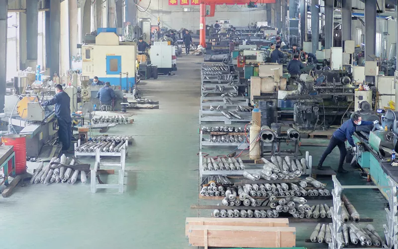
Nanhaiya’s published production equipment page lists CNC saws, CNC lathes, CNC drilling and milling machines, and five-axis machining centers. Equipment availability supports production, but the buyer should still ask how datums, intermediate checks, treatment allowance and final inspection connect to the approved screw drawing.
A typical review should close five questions before production:
- Which drawing and revision govern the order?
- Which dimensions came from the original design, the sample and the manufacturer’s reconstruction?
- What base material and surface system are specified?
- Which characteristics are critical to assembly and function?
- What documents and measured results will be supplied before shipment?
For a wider view of machining, surface engineering and inspection stages, see the screw and barrel manufacturing process guide.
Connect the Replacement to the Correct Single Screw Product Route
Nanhaiya’s single screw product category is the primary commercial route for current models and project inquiries. Application pages can help organize the initial conversation, but the final replacement still requires machine and process verification.
LDPE/HDPE Film Single Screw
Use this route when the replacement belongs to a film extrusion line.
Transparent Granulation Single Screw
Use this route for a granulation application where melt and surface condition deserve specific review.
Super Wear-Resistant Single Screw
Use this route when the documented problem is abrasive or corrosive service.
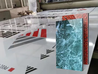
Aluminum-Plastic Panel Single Screw
Use this route for a screw installed in an aluminum-plastic panel production line.
Replacement Single Screw RFQ Checklist
A useful RFQ lets the supplier identify missing data before quoting. Attach the evidence rather than compressing it into one message.
- Machine manufacturer, model, serial reference and nameplate photo.
- Original drawing, drawing number and revision, if available.
- Full-length and close-up photos of the removed screw.
- Overall length, working length and all mechanical interface dimensions.
- Outside-diameter profile, pitch, flight width, root or channel measurements and special features.
- Barrel-bore measurements and the method used to obtain them.
- Resin grade, filler or fiber, additives, recycled content and contamination risk.
- Target product, normal output, speed, temperatures and known pressure data.
- Current symptoms, service history and mapped wear locations.
- Required base material, surface treatment and inspection evidence.
- Quantity, packaging needs and any mating components included in the order.
Before production, ask for an approval drawing that clearly identifies the revision and units. Before shipment, request the agreed dimensional results and treatment or material records. The document package should identify the actual part rather than provide a generic certificate with no traceable link to the work order.
Frequently Asked Questions
Can a replacement single screw be made from a worn sample?
A worn sample can provide interface dimensions and clues to the original geometry, but it should not be copied blindly. Wear, bending, corrosion and previous repair can change the measured profile. Combine the sample with the machine model, any original drawing, barrel-bore measurements, process data and a documented review of which dimensions are still trustworthy.
Is the extruder model enough to order a replacement screw?
Usually not. Machines of the same model may have different screw revisions, drive connections, feed-throat layouts or application-specific geometries. The model and serial reference are useful starting points, but the supplier should also confirm physical interfaces, working length, processed material and the required screw design.
Should the barrel be measured when only the single screw is being replaced?
Yes. The new screw will operate inside the existing barrel, so the current bore condition affects working clearance. Measuring only the worn screw can hide the combined wear of the pair. Record the barrel bore at agreed axial and circumferential positions and evaluate whether replacing one component is technically reasonable.
What should be included in a replacement single screw RFQ?
Include the machine manufacturer, model and serial reference; controlled drawings or sample photos; screw and barrel measurements; drive-end and tip details; resin, fillers, additives and recycled content; target output and operating conditions; known failure symptoms; requested material or surface system; quantity; and the inspection documents required before shipment.
Need a Replacement or Custom Single Screw?
Send your machine nameplate, drawing or sample photos, material formulation and current production problem. Zhoushan Nanhaiya Plastic Machinery Co., Ltd. can review the available information and identify what still needs confirmation before quotation.
The fastest useful starting package includes the machine model, main dimensions, barrel condition, resin and fillers, target output, quantity and the documents you expect with the finished part.