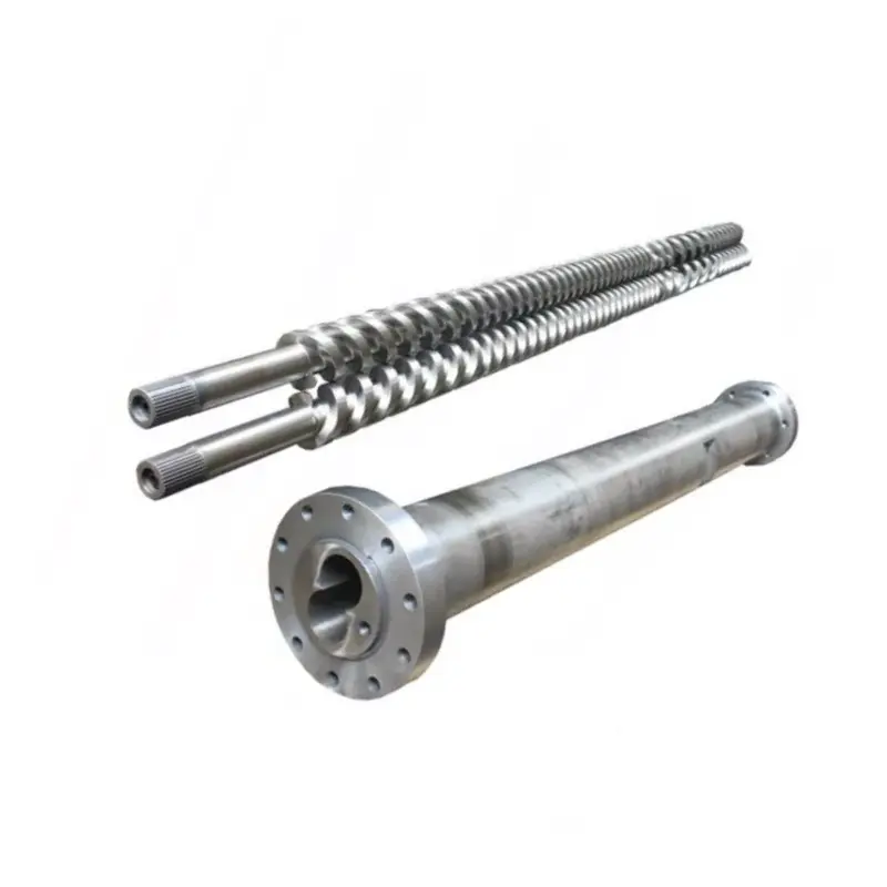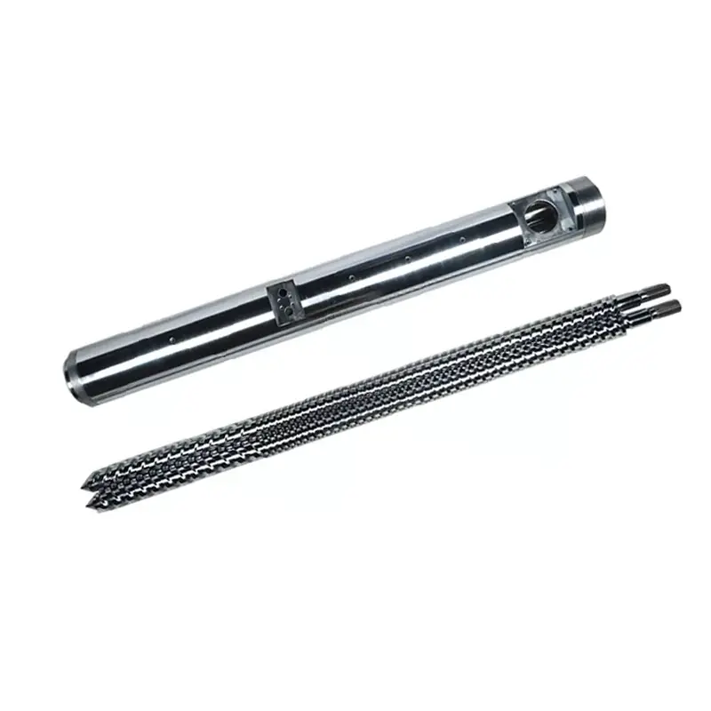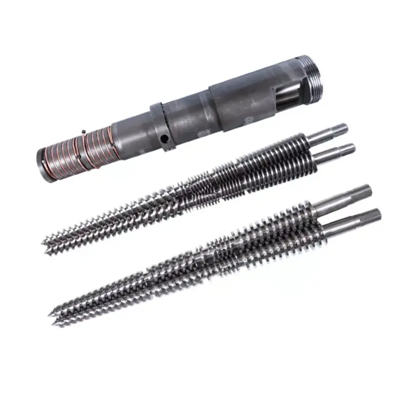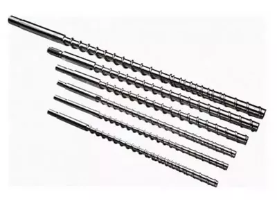

A pipe die head must fit more than a nominal diameter. It has to match the polymer, formulation, pipe standard, output, extruder connection, calibration system and the way your operators change sizes. This guide turns those inputs into a purchase specification for PVC, PE, CPVC, PP and PPR pipe production.
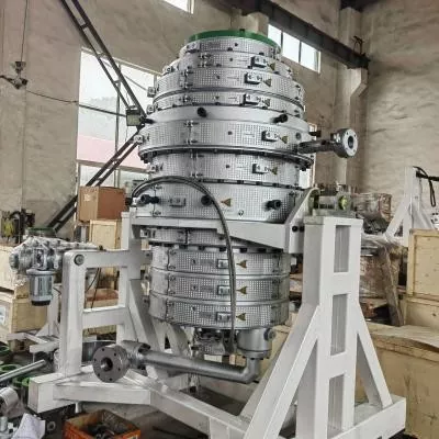
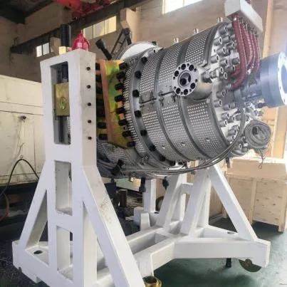
To buy a pipe extrusion die head, send the supplier five matched data sets: the material and formulation; the pipe standard, diameter and wall range; output and line speed; the extruder flange and melt-inlet interface; and the downstream calibrator, vacuum, cooling and haul-off arrangement. A request that gives only "PVC pipe, 110 mm" is not ready for engineering.
The most important contract point is the acceptance condition. Name the actual production material, pipe size, stable output, line speed, heating and sensor setup, allowable wall variation, outside diameter, ovality, surface condition and required product tests. The die head shapes the hot melt, but it cannot by itself guarantee the final cooled pipe.
The first decision is not the die diameter
The first decision is the production envelope. One head may run a group of nearby sizes with changeable dies and mandrels. A very broad size range can produce compromises in flow, residence time, adjustment, head pressure and changeover work. The correct range depends on the material and rate, not only on which inserts can physically fit inside the body.
We divide every inquiry into three boundaries. The product boundary covers pipe material, standard, diameter and wall. The process boundary covers output, speed, temperature and pressure. The mechanical boundary covers the flange, centerline, heaters, sensors, lifting and downstream position.
| Buyer input | Why it changes the die head | Evidence to send |
|---|---|---|
| Polymer and complete formula | Changes viscosity, heat sensitivity, slip, wear, corrosion risk, residence-time limit and cleaning method | Resin grade data sheet, formulation percentages and sample |
| Pipe standard and application | Defines the finished product that the line must produce and test | Exact standard number, edition, market and internal drawing |
| OD, wall, SDR or schedule range | Sets the annular flow area, tooling family and practical change-part range | Size table with minimum, normal and maximum products |
| Net output and line speed | Changes flow velocity, pressure, heating load, residence time and downstream cooling demand | Stable saleable kg/h for each critical size |
| Extruder and adapter interface | Determines the inlet geometry, bolt pattern, register, seal, center height and support | Controlled drawing plus measured photos of the existing machine |
| Calibration and cooling system | Affects drawdown, final OD, ovality, wall distribution and start-up behavior | Calibrator drawings, vacuum tank data, cooling length and haul-off position |
| Changeover plan | Determines which parts are removable, how they are centered and how safely operators handle them | Change frequency, cleaning method, crane capacity and target downtime |
Our factory view: we do not regard a nominal pipe diameter as a sufficient die-head specification. If a buyer gives us only the resin name and OD, we ask for the wall series, formula, output, extruder interface and sizing method before fixing the flow path. A fast quotation based on missing inputs usually moves the unanswered questions into commissioning.
Start with the finished pipe standard
A die head is production tooling. It is not a pipe certification. The buyer must identify the exact product standard and edition, while the supplier must translate the pipe envelope into a flow path, tooling set and adjustment method. Final compliance is proved on the finished pipe by the tests required for its market and application.
For common water-pipe projects, three useful official references are ISO 1452-2:2009 for PVC-U pipes, ISO 4427-2:2019 for PE pipes and ISO 15874-2:2013 for PP pipes used in hot and cold water installations. Check the current edition, amendments and national adoption when the contract is prepared.
| Pipe family | Official starting reference | Information the die-head RFQ still needs |
|---|---|---|
| PVC-U pressure pipe | ISO 1452-2 or the required national equivalent | PVC dry-blend formula, pipe series, nominal OD, wall table, socketing allowance, output, line speed and surface requirements |
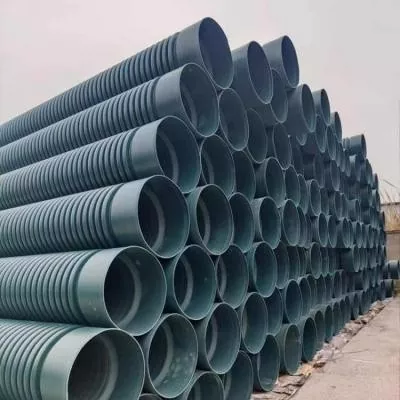
| PE pressure pipe | ISO 4427-2 or the required national equivalent | Exact PE compound, SDR range, OD range, solid or co-extruded construction, stripe or layer arrangement, output and cooling system |
| PP or PPR hot and cold water pipe | ISO 15874-2 or the required national equivalent | Exact PP grade, pipe dimension class, service application, layer construction, diameter and wall range, output and calibration method |
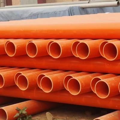
| Electrical conduit or industrial tubing | The buyer's applicable national, industry or customer specification | Material formula, stiffness or functional target, geometry, color, print or stripe, test plan and allowable surface defects |
Do not write "according to international standard" in the RFQ. Name the document, part, edition and local adoption. Then attach your finished-pipe drawing and inspection plan. Similar nominal sizes can have different wall ranges, test conditions and identification requirements.
One more separation matters. Potable-water approval concerns the finished piping product and its wetted materials. Ordering a die head from Nanhaiya does not transfer a drinking-water approval to the buyer's pipe. Resin approval, compound control, production records and third-party certification remain part of the pipe manufacturer's compliance system.
Specify the actual formula, not just PVC or PE
Nanhaiya's pipe extrusion die head is offered for PVC with additives, PE, CPVC and PP. Those names define material families. They do not tell us the melt viscosity, filler loading, stabilizer system, recycled content, processing window or tendency to plate out.
For PVC, send the full dry-blend recipe by weight and the mixing condition. Calcium carbonate level and particle treatment, lubricant balance, stabilizer system, impact modifier, processing aid, pigment and rework percentage can all change wall appearance, head pressure and deposit behavior.
For PE or PPR, send the exact compound grade and current supplier data sheet. Include melt mass-flow or viscosity information as published for that grade, density, additives, carbon-black or color system, regrind limit and whether identification stripes or functional layers are co-extruded.
PVC and CPVC
Heat history and residence time deserve close attention. The flow path should avoid unnecessary hold-up, and the heating plan must support controlled start-up and cleaning. Formula changes should be disclosed before manufacture.
PE
Grade, melt strength, output and cooling capacity act together. A high-output PE head needs stable circumferential flow and an appropriate sizing system, not simply a larger annular gap.
PP and PPR
State the exact resin and service product. Hot and cold water pipe, industrial tube and multilayer construction can require different tooling, cooling and acceptance conditions.
Our factory view: when a production team changes filler, resin grade or recycled percentage after the tooling is approved, the die has not suddenly become inaccurate. The process input has changed. We record the reference formulation on the technical agreement so future troubleshooting starts from a known condition.
The die opening is not the final pipe size
A hot annular melt does not leave the die and remain geometrically fixed. It may swell at the exit, draw down under haul-off, contact the calibrator, shrink during cooling and continue changing as its temperature equalizes. That is why a nominal 110 mm pipe does not automatically use a 110 mm die opening.
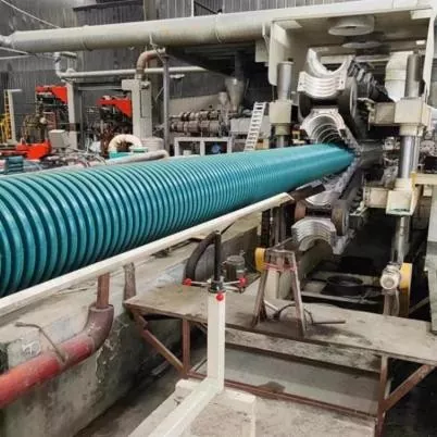
The final result comes from a system: extruder output, melt temperature and pressure, die and mandrel geometry, circumferential heat balance, centering, air path, calibrator, vacuum, cooling and haul-off speed. If these parts are purchased from different suppliers, the buyer should assign one controlled interface drawing and one acceptance responsibility matrix.
| Control element | What it directly influences | What it cannot prove alone |
|---|---|---|
| Die and mandrel flow path | Annular melt distribution, pressure loss, residence behavior and initial tube shape | Final cold OD, wall, ovality or pressure performance |
| Mandrel centering adjustment | Initial circumferential gap and correction of wall distribution | A stable result when temperature, flow or downstream alignment keeps drifting |
| Heater-zone arrangement | Thermal control around and along the head | The actual melt temperature without a defined measurement method |
| Calibrator and vacuum tank | External sizing, early cooling and shape support | Uniform wall when the incoming melt tube is unstable |
| Cooling system | Solidification rate, dimensional stability and residual heat removal | Good geometry when water temperature or flow is uncontrolled |
| Haul-off | Line speed, drawdown and steady transport | Correct dimensions when the puller is misaligned or speed fluctuates |
Useful sizing rule: specify the smallest and largest pipe, but engineer around the difficult operating corners. These are often the largest pipe at high output, the thinnest wall at high line speed, a low-output small size that increases residence time, and the product with the tightest wall or surface requirement.
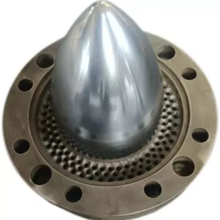
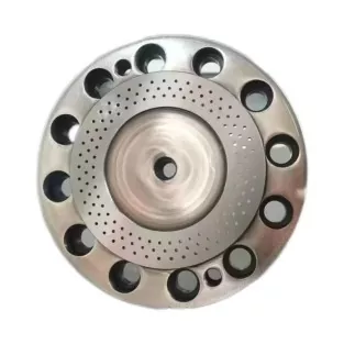
Nanhaiya offers adjustable mandrels, cooling-channel options and replaceable liners on its pipe die-head range. Use those options for a defined reason. Adjustment is useful when operators have a repeatable centering method. Replaceable wear components are useful when their scope, spare quantity and replacement procedure are clear.
Lock the extruder interface before machining starts
A pipe die can have an excellent internal flow path and still fail to install because the inlet, register, bolt pattern, seal or center height was assumed. Replacement projects are especially vulnerable because machine drawings may be old, modified or unavailable.
We prefer three forms of evidence: the original controlled drawing, fresh measurements and clear photos with a scale reference. If the three disagree, resolve the conflict before the manufacturing drawing is released.
- Extruder make, model and screw configuration
- Screw diameter and rated output range
- Discharge or adapter flange drawing
- Register diameter, depth and tolerance
- Bolt quantity, thread, pitch circle and orientation
- Sealing-face geometry and gasket method
- Melt-inlet diameter and transition length
- Required breaker plate or screen interface
- Pressure-sensor port size and location
- Melt-temperature sensor type and insertion
- Heater voltage, frequency, power and connectors
- Thermocouple type and controller compatibility
- Die-head center height and flow direction
- Support frame, wheels, rails or lifting points
- Available installation and maintenance clearance
- Distance to calibrator and alignment reference
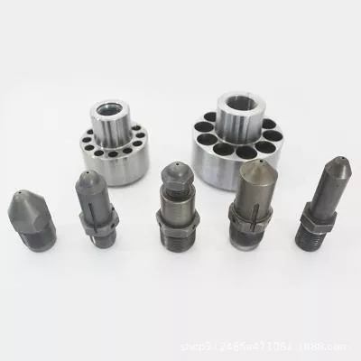
Nanhaiya manufactures customizable barrel flanges and die-head components, so the adapter can be discussed with the head instead of left as an installation surprise. For a complete line project, align the die interface with the selected plastic extruder machine, controls and downstream equipment.
Our factory view: a phone photo of a flange helps us understand the layout, but it does not define a bolt circle or register fit. We use the photo to find questions. We use a signed drawing to cut metal. That distinction prevents a small interface mistake from delaying an entire installation.
Choose construction around the material and cleaning duty
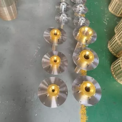
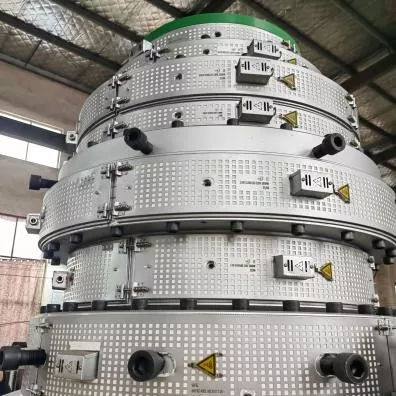
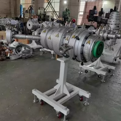
Nanhaiya's dedicated pipe die head uses high-strength alloy steel with hardened surfaces and is produced by precision CNC machining and heat treatment. Its general extruder die head page lists 38CrMoAl, nitriding and a surface hardness of HV950 to HV1000.
Those values are useful starting data, but the approved specification should still identify the exact component material, treatment scope, finished hardness criterion, flow-surface finish, dimensional inspection and any corrosion requirement. A hardness value on one component should not be copied to every fastener, heater cover or structural part.
| Service condition | Procurement concern | What to define in the quotation |
|---|---|---|
| Filled PVC | Abrasive mineral filler, deposits and cleaning frequency | Formula, filler level, wetted-component material and treatment, replaceable-wear scope and cleaning method |
| CPVC or heat-sensitive compound | Thermal history, hold-up and material degradation | Processing window, flow-path concept, heating zones, sensor points, start-up and shutdown procedure |
| Carbon-black PE | Stable distribution, surface quality and long runs | Compound grade, output range, pressure window, heater arrangement and cleaning access |
| Recycled content | Contamination, viscosity variation and abrasive particles | Source, maximum percentage, filtration plan, sample, expected variation and acceptance limits |
| Frequent color changes | Hold-up, access, change-part handling and scrap | Color sequence, cleaning material, allowed change time, purge procedure and removable parts |
Harder is not a complete material strategy. Surface hardness, case depth, substrate toughness, corrosion behavior, finish and repair method must suit the component and process. Ask the supplier to list what is treated, how it is verified and which inspection record comes with the order.
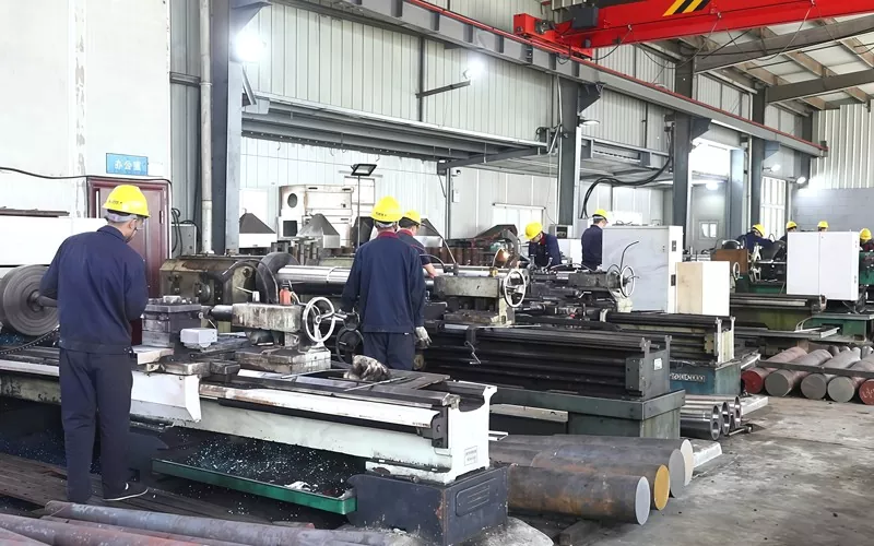
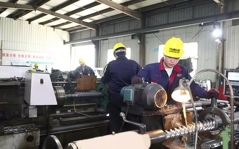
Review Nanhaiya's production equipment, certificates and technical service during supplier qualification. Installation guidance and long-term maintenance advice can be included in the agreed support scope.
Make size changeover part of the purchase calculation
A lower tooling price can be expensive if every change ties up a crane, damages heaters or requires repeated trial-and-error centering. Ask how the die and mandrel are removed, where hot parts are placed, which fasteners are handled, how alignment is restored and which seals or consumables are replaced.
| Changeover question | Why the buyer should care | Contract output |
|---|---|---|
| Which sizes share one body? | Shows the real number of heads and change-part sets | Compatibility matrix by pipe OD, wall range and material |
| What must cool before removal? | Affects downtime and handling safety | Written temperature and handling procedure |
| How are die and mandrel centered? | Affects start-up scrap and wall correction | Adjustment diagram, reference positions and training |
| Which tools and lifting devices are required? | Prevents unsafe improvised handling | Tool list, part weights, lifting points and fixture drawings |
| Which parts are routine spares? | Reduces downtime after thread, seal, heater or sensor damage | Two-year recommended spare list priced by item |
| How is the flow path cleaned? | Changes labor, surface risk and color-change scrap | Approved cleaning tools, materials and disassembly steps |
For a mixed product schedule, calculate changeover cost by hours, labor and start-up scrap. If a plant changes between two distant pipe sizes several times per week, two complete heads may protect more production time than one body with many inserts. If changes are infrequent and the range is compact, a shared body can be sensible.
Our factory view: we ask who will change the tooling and what lifting equipment is available. A design that works on a clean assembly bench may be awkward beside a hot extruder and a vacuum tank. Operator access is an engineering input, not an after-sales detail.
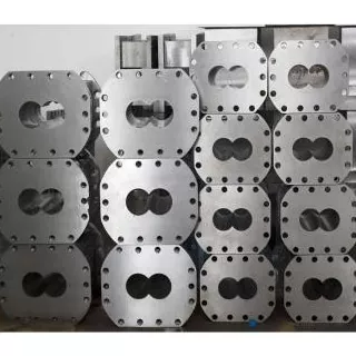
Use pipe defects to find the responsible process zone
When a pipe runs off specification, operators often adjust the die first because its centering bolts are visible. That can temporarily improve one reading while hiding a temperature, extruder or downstream problem. Record the defect around the circumference and along the pipe length before making several changes at once.
| Observed defect | Die-head checks | Upstream and downstream checks | Buying lesson |
|---|---|---|---|
| One side consistently thicker | Mandrel centering, flow-path deposits, damage, heater balance and assembly alignment | Extruder surging, calibrator alignment, vacuum distribution, cooling and haul-off alignment | Require accessible centering, temperature zones and an alignment reference |
| Wall changes around and along the pipe | Loose adjustment, thermal cycling, unstable pressure or uneven flow | Feeding, screw output, line-speed control, vacuum and water-temperature stability | Accept a stable operating window, not one short set of measurements |
| Long surface lines | Contamination, deposit, scratch or damaged die-lip surface | Unmelted particles, filtration, calibrator damage and handling marks | Define cleaning tools, filter plan, surface inspection and spare tooling |
| Yellow, brown or black streaks | Dead zones, deposits, excessive local heat and long residence time | Contaminated feed, barrel deposits, screw wear and shutdown practice | Review the full melt path and cleaning routine before copying the old geometry |
| High head pressure | Restricted annular gap, low temperature, blockage or unsuitable flow path | Screen restriction, material viscosity, output demand and sensor condition | State the pressure measurement point and operating limit in the specification |
| Pipe ovality | Uneven exit flow or initial tube position | Calibrator wear, vacuum, cooling balance, support and haul-off alignment | Final ovality belongs to the complete-line acceptance test |
| Rough inner surface | Mandrel finish, deposits, temperature and flow behavior | Material moisture, dispersion, degradation and output stability | Include both internal and external surface criteria in the sample approval |
One-change rule: record the baseline, change one controlled variable, wait for the material to travel through the line, mark the affected pipe and measure again. Random adjustment of temperatures, centering, vacuum and haul-off at the same time destroys the evidence needed to identify the cause.
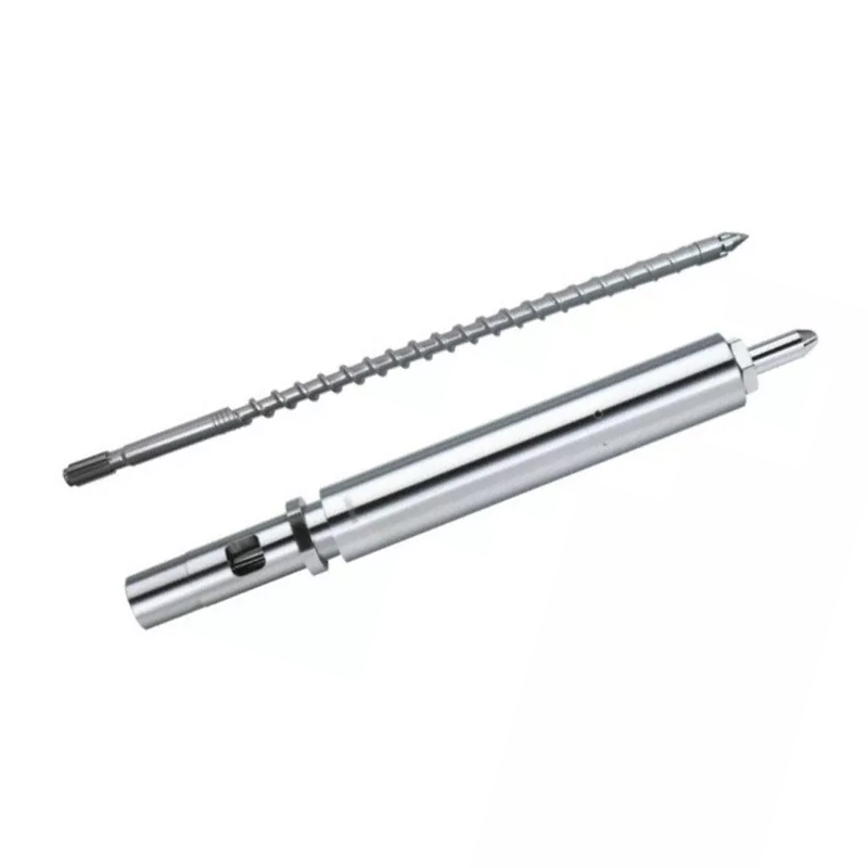
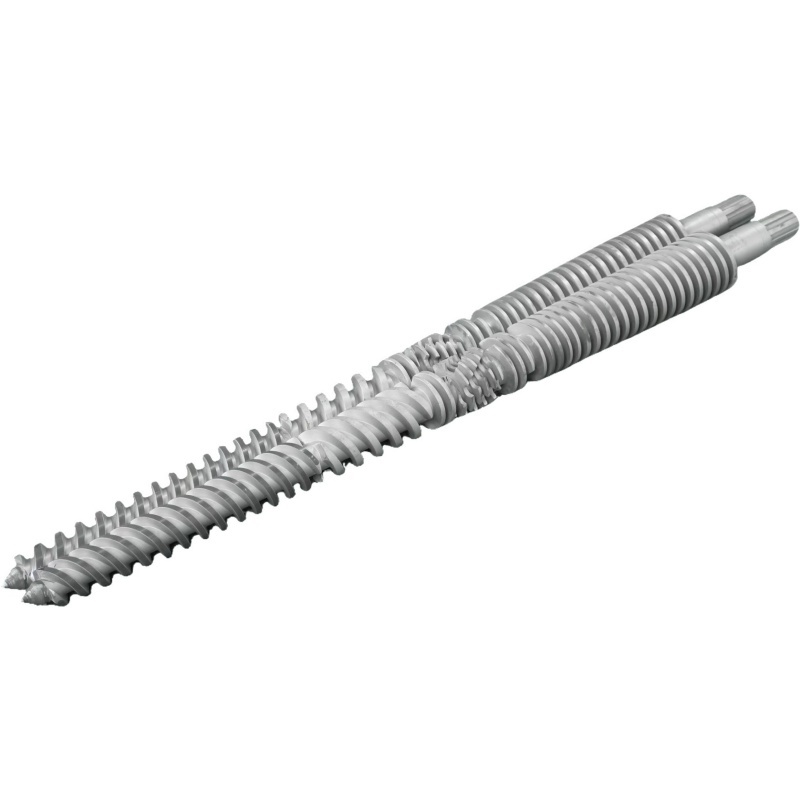
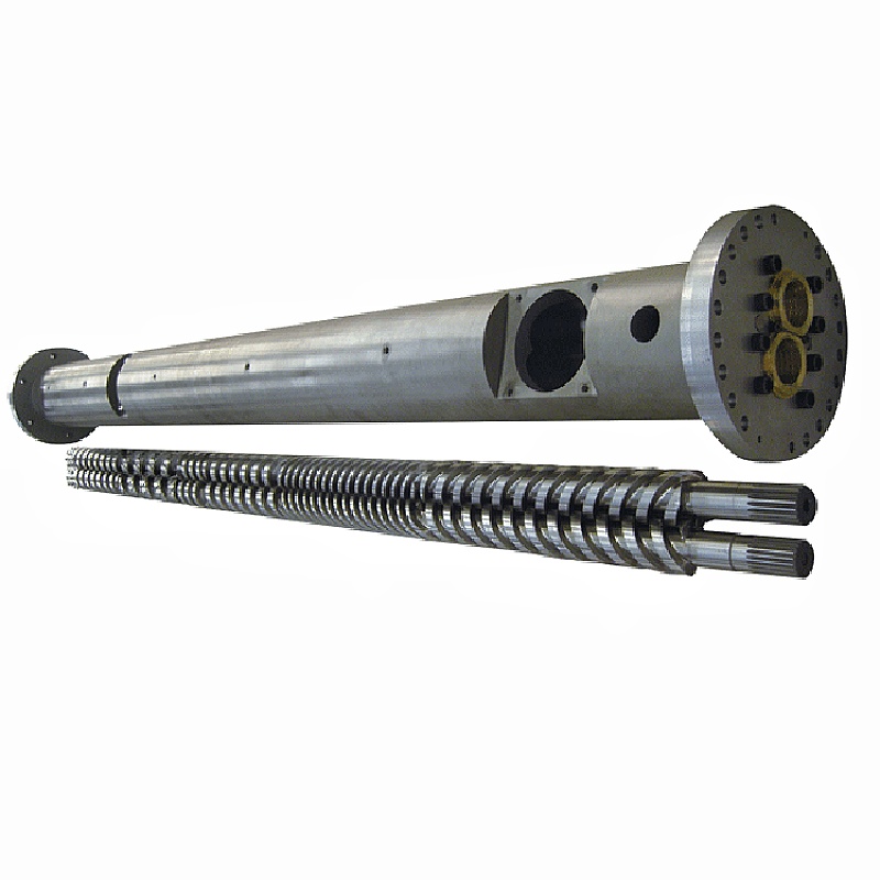
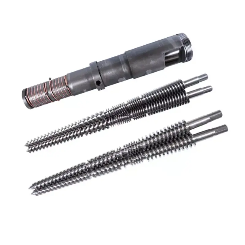
If output or melt pressure is unstable before the head, also inspect the screw and barrel. Nanhaiya supplies PVC pipe single screws, PVC pipe parallel screw barrels and PVC pipe conical twin-screw barrels. The die should not be redesigned to compensate for a worn or unsuitable plasticizing section.
Pipe extrusion die head RFQ checklist
A complete RFQ lets the buyer compare engineering scope instead of comparing a low base price with an inclusive quotation. Put the following items in one revision-controlled package.
- Identify the products. List every pipe OD, wall range, SDR or schedule, layer construction, color and application. Mark the normal product and the most difficult size.
- Name the standard. Give the exact standard, part, edition, national adoption and internal drawing. Attach the finished-pipe inspection plan.
- Disclose the material. Provide the full PVC formula or exact PE, PP or PPR grade, additives, filler, pigment, recycled content and supplier data sheets.
- Define rate. Give net saleable output and line speed for each critical product, plus the available cooling capacity and normal operating schedule.
- Describe the extruder. State single, parallel twin or conical twin screw; screw diameter; motor power; normal melt pressure and temperature; adapter layout; and current process limits.
- Control the interface. Attach the flange, register, bolt circle, sealing face, melt inlet, center height, sensor-port and support drawings.
- Specify electrical details. List heater voltage and frequency, thermocouple type, connector standard, controller compatibility, cable length and hazardous-area requirement if applicable.
- Show the downstream line. Include calibrator dimensions, vacuum tank, cooling length, spray or immersion arrangement, haul-off type, centerline and distance from die exit.
- Choose the changeover scope. List change-part sets, spare heaters and sensors, seals, fasteners, handling tools, storage racks and desired size-change procedure.
- Define documents. Request assembly and part drawings, bill of materials, material and heat-treatment records, dimensional inspection, electrical list, operating instructions and spare-parts list.
- Write the acceptance test. Name the resin, formula, pipe size, run duration, output, line speed, process records, dimension sampling and pass/fail criteria.
- Clarify support. Agree on installation guidance, commissioning responsibility, operator training, remote assistance and the boundary between die-head and complete-line performance.
Replacement warning: a worn die may no longer preserve its original dimensions. Measure the machine interface and a good retained pipe, find any original drawings and explain why the old head is being replaced. Copying every worn dimension can reproduce the same flow or alignment problem.
The screw configuration must also match the material duty. Browse Nanhaiya's single screws, parallel twin screws and conical twin-screw barrels when the inquiry covers the full plasticizing section. For accessories and connected tooling, use the extrusion spare-parts range.
Accept the head on the production condition you plan to sell
Dimensional inspection proves that the manufactured components match the drawing. It does not prove how a specific compound will flow through the complete line. A sound acceptance plan has two parts: component verification and a production run.
| Acceptance stage | What to verify | Record to keep |
|---|---|---|
| Document review | Approved drawing revision, bill of materials, change-part matrix, heater and sensor list, manuals and spare scope | Signed document register |
| Component inspection | Critical interfaces, concentric features, sealing faces, fasteners, ports, material, treatment and visible flow-surface condition | Dimensional and material or treatment records specified in the order |
| Assembly check | Fit, orientation, heater installation, sensor insertion, centering movement, support, lifting and access | Assembly checklist with photographs |
| Heat-up check | Zone identification, controller response, sensor reading, current draw and thermal stability | Zone map and stabilized readings |
| Production run | Agreed material, pipe size, output, line speed, temperature, melt pressure, motor load, vacuum and cooling conditions | Time-based process sheet and retained samples |
| Pipe inspection | OD, wall at multiple clock positions, ovality, mass per length, inner and outer surface, straightness and required standard tests | Inspection report tied to sample position and production time |
| Routine operation | Start-up, centering correction, a normal stop, safe disassembly or one agreed size change | Operator sign-off and open-item list |
Use the buyer's normal formulation when practical. If a substitute material is required, record the difference and limit what the test proves. A successful PE run does not validate a PVC formula, and a thick-wall low-speed product does not prove a thin-wall high-speed condition.
Our factory view: we prefer a stable run with traceable measurements over a brief display at maximum output. The pressure should settle, wall readings should remain controllable, heaters should not cycle abnormally and the cooled pipe should meet the agreed inspection. That result gives both sides a useful handover point.
Frequently asked questions
What information is required to quote a pipe extrusion die head?
Send the polymer grade and formula, pipe standard, complete size and wall range, target output and line speed, extruder type, melt inlet and flange drawing, heater voltage, sensor requirements, downstream calibration details, preferred change parts and an acceptance plan. Photos and measured drawings of the current connection are also useful for replacement projects.
Can one pipe die head run PVC, PE and PPR?
A shared outer body may be technically possible in a narrowly defined project, but PVC, PE and PPR do not create the same flow, thermal or sizing conditions. We first compare the full formulation, output, size range, flow-path requirements and cleaning method. Separate tooling or a separate head can be the safer production choice.
Does the pipe die diameter equal the final pipe diameter?
Usually no. The hot tube changes after leaving the die because the melt swells, draws down, enters the calibrator and cools. The required die and mandrel dimensions must be designed with the material, output, line speed, vacuum sizing and cooling system, rather than copied directly from the nominal pipe size.
Can the die head alone guarantee pipe wall thickness and ovality?
No. The die head establishes the annular melt distribution, but final wall thickness and ovality also depend on melt stability, centering, temperature balance, calibrator condition, vacuum, cooling, haul-off alignment and line speed. Acceptance should test the complete operating line.
Which material does Nanhaiya use for extrusion die heads?
Nanhaiya's general extruder die head page lists 38CrMoAl with nitriding and surface hardness of HV950 to HV1000. The dedicated pipe extrusion die head is described as alloy steel with hardened surfaces. Final material, heat treatment and wetted-surface requirements should be confirmed for the resin, additives and cleaning method in the approved specification.
Should I buy one die head with many size inserts or several complete heads?
Use change parts when the size range, output and cleaning routine allow one body to cover the job without excessive adjustment. Separate heads can make sense when products differ greatly in diameter, polymer, output, layer structure or changeover frequency. Compare total changeover time and production risk, not tooling price alone.
How should a pipe extrusion die head be accepted?
Start with drawing, material, treatment, heater, sensor, flange and flow-path checks. Then run the agreed production material at the specified pipe size, output and line speed. Record temperatures, melt pressure, wall readings around the circumference, outside diameter, ovality, surface condition, mass per length and any tests required by the target pipe standard.
What causes one side of an extruded pipe wall to be thicker?
Possible causes include die or mandrel mis-centering, circumferential temperature imbalance, uneven melt flow, deposits or damage in the flow path, unstable extruder output, calibrator misalignment, uneven vacuum or cooling, and haul-off misalignment. Check the trend before using centering bolts to hide a downstream problem.
Technical content prepared from Nanhaiya's current product, equipment and service information, supported only by official ISO pipe-standard pages. Final die geometry, material, treatment, dimensions and acceptance criteria are defined by the approved project specification.