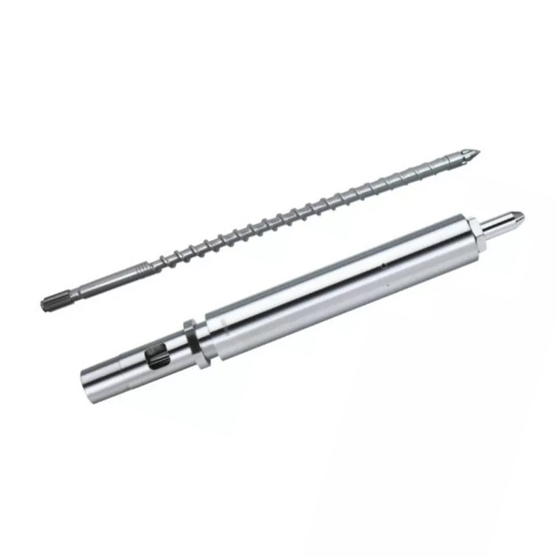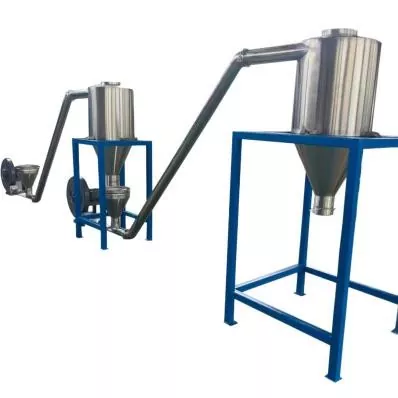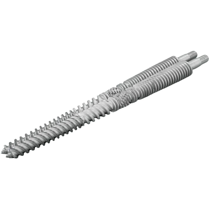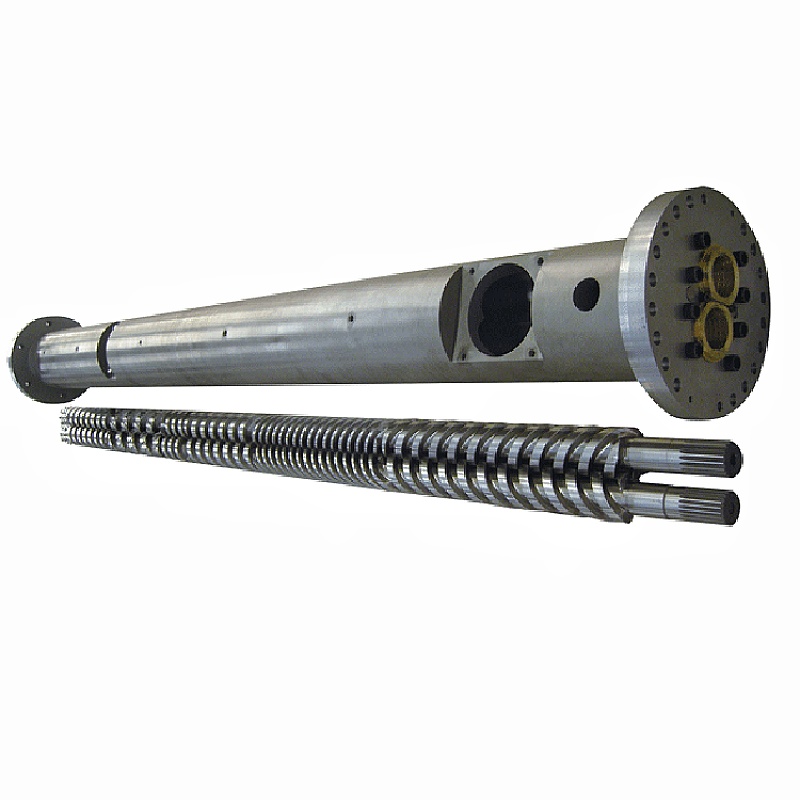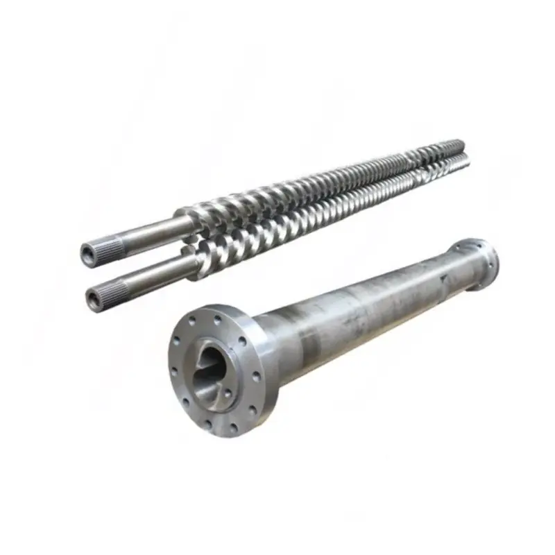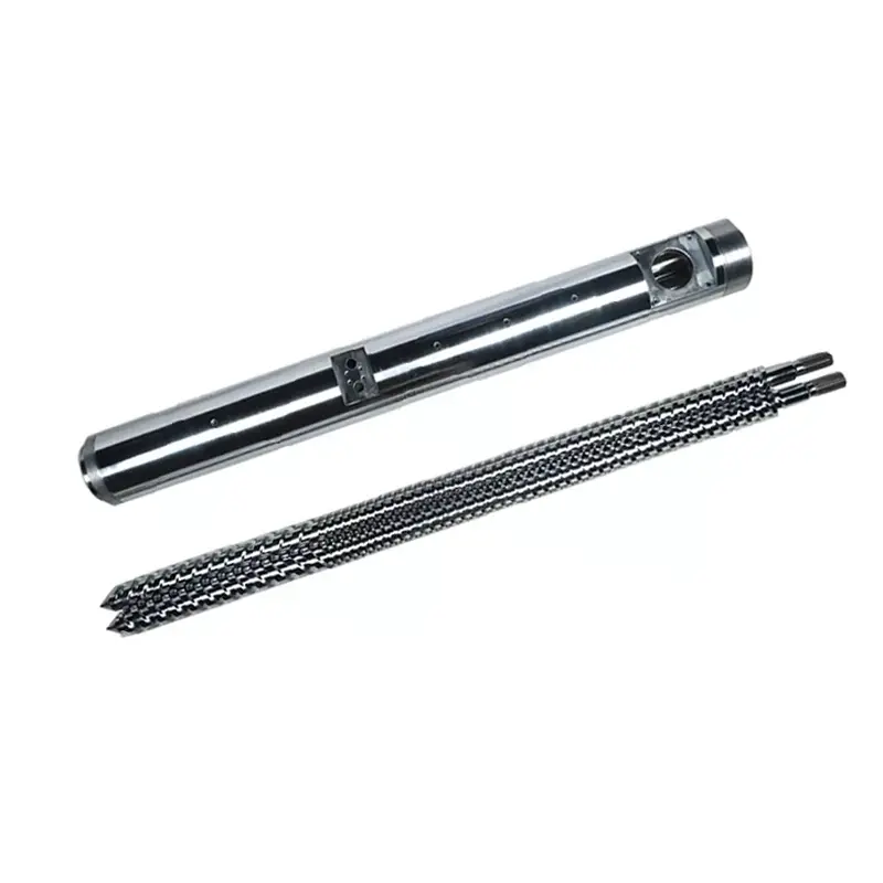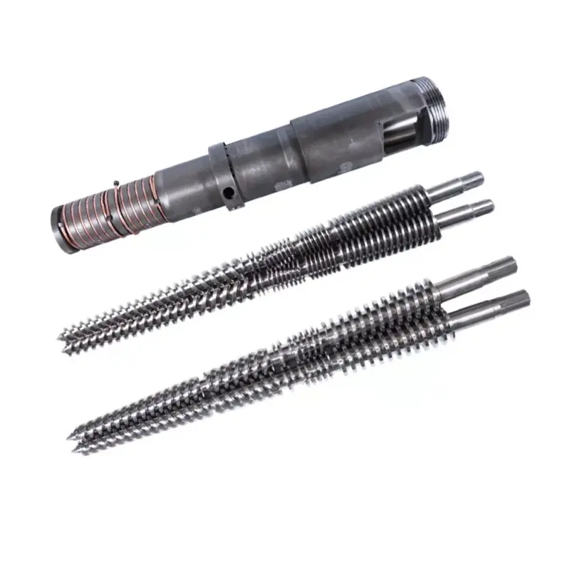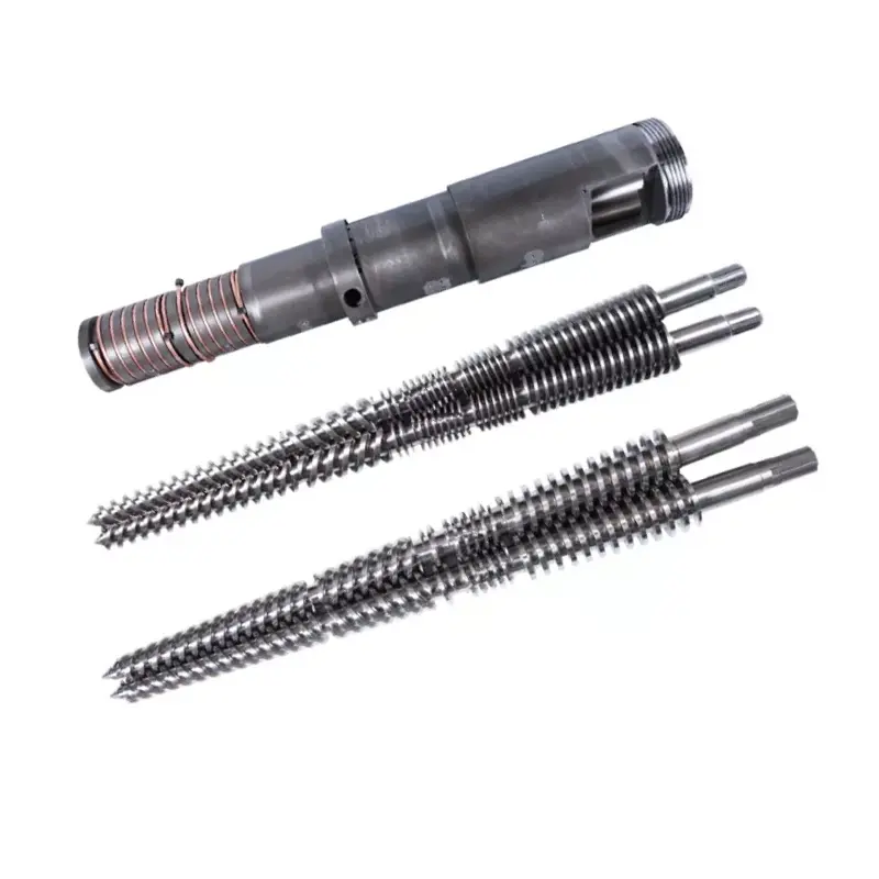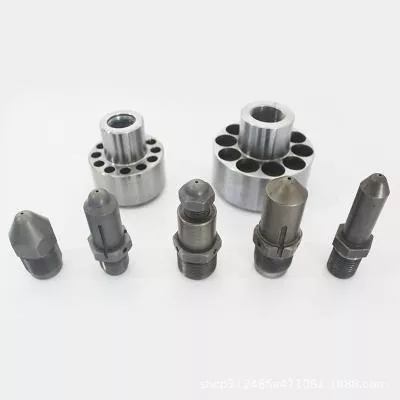

A WPC mould cannot be selected from a product photo and outside dimensions. The tooling must match the wood-plastic formula, profile section, output, extruder discharge, calibration method, cooling line and the performance tests used for the finished board or profile.

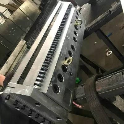
Quick answer
To buy a WPC extrusion mould, send the final cross-section with tolerances, the complete polymer and wood-filler formula, material preparation method, target output and line speed, extruder interface, downstream cooling layout and a finished-product acceptance plan. Mark visible surfaces, critical walls, internal ribs, cavities, radii and any embossing or sanding allowance on the drawing.
Do not accept the tooling from a dry dimensional report alone. Run the agreed formula through the intended line, let the profile cool, then measure dimensions, wall and rib thickness, straightness, twist, surface condition and mass per length. Product performance tests remain the responsibility of the finished-product manufacturer.
Buy a forming system, not an isolated block of steel
The extrusion mould creates the hot profile as the WPC melt leaves the extruder. That profile is still soft and capable of changing shape. Calibrators, cooling sections, support, haul-off and cutting equipment then hold and stabilize it. A die that looks correct on a bench can produce an unstable profile if those downstream parts do not match it.
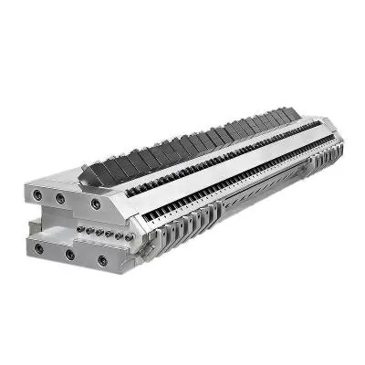
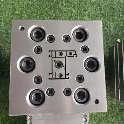
Nanhaiya's WPC mould range uses steel bodies with hardened and polished surfaces. The moulds are CNC machined and heat treated, and optional cooling channels are available. The product scope covers sheets, boards and profiles, including decking, fencing, panels and outdoor-furniture components made from PE or PP with wood filler.
| Purchase item | Its job | What must appear in the quotation |
|---|---|---|
| Adapter and inlet | Connects the extruder discharge to the profile flow path | Flange, bolt pattern, register, seal, melt inlet, center height, heater and sensor details |
| Extrusion die | Distributes melt and forms the hot profile section | Body and insert drawings, material, treatment, heating zones, flow-surface finish and adjustment points |
| Calibrator or sizing tooling | Supports critical surfaces and dimensions during early cooling | Number of sections, contact surfaces, vacuum or water connections, adjustment and mounting |
| Cooling tooling | Removes heat while the profile is supported | Cooling channels, water requirements, tank or plate layout and connection sizes |
| Change parts | Allows planned product variants or replaces routine wear items | Drawing numbers, compatibility matrix, spare quantity and change procedure |
| Handling and support | Positions the tooling and protects the extruder connection | Part weights, lifting points, stand, rails, centerline adjustment and storage fixtures |
| Documentation | Controls manufacture, installation, operation and future replacement | Approved drawings, bill of materials, inspection records, manual and spare-parts list |
Our factory view: the phrase "one set of WPC mould" is too vague for price comparison. One supplier may quote only the heated die body. Another may include the adapter, several calibrators, cooling plates, supports, spare heaters and commissioning guidance. We ask the buyer to compare a line-item scope before comparing the total.
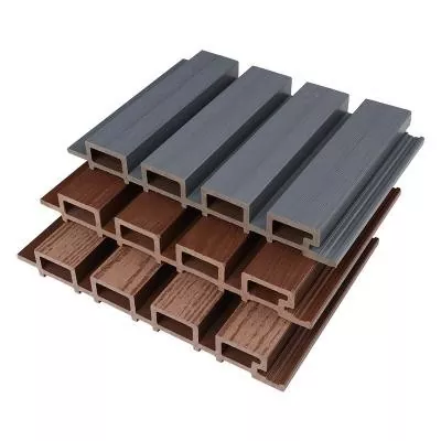
The final profile drawing is the starting point
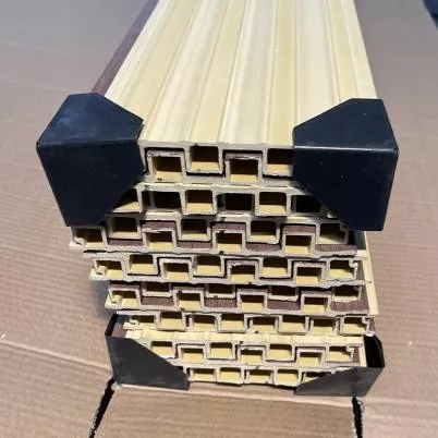
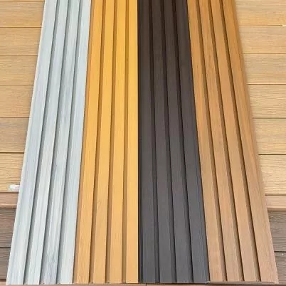
A catalog photo shows the product family, but it hides the information that controls tooling. We need a section view with dimensions and tolerances. The drawing should also identify the surfaces that mate with clips, fasteners, frames or other profiles because those features often deserve tighter control than a decorative face.
For a hollow profile, give every wall and web dimension. Do not leave the internal cavities as an artistic pattern. Their geometry affects material distribution, cooling, stiffness, profile weight and how the section behaves under haul-off.
- Overall width, height and profile orientation
- Wall thickness on every outside face
- Internal web thickness and position
- Cavity size, quantity and geometry
- Corner and internal radii
- Grooves, tongues, clips and fastener zones
- Critical tolerances and inspection datums
- Allowed bow, twist and straightness
- Target mass per unit length
- Visible faces and surface-defect limits
- Embossing, sanding or brushing allowance
- Cut length and downstream cutting method
- Solid, hollow, capped or co-extruded construction
- Approved master sample and revision date
Do not machine the die opening as a copy of the cold finished profile. The hot WPC section can change through die swell, drawdown, calibration and cooling. Tooling compensation must be developed around the actual formula, output and downstream system.
Our factory view: a clean 3D rendering is useful for sales, but it is a poor manufacturing document. We ask which surfaces assemble with another part, which wall controls strength, which face the customer sees and where the plant can accept variation. That priority map is more useful than putting the same tight tolerance on every line.
WPC is a family of formulas, not one raw material
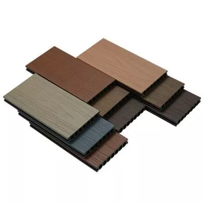
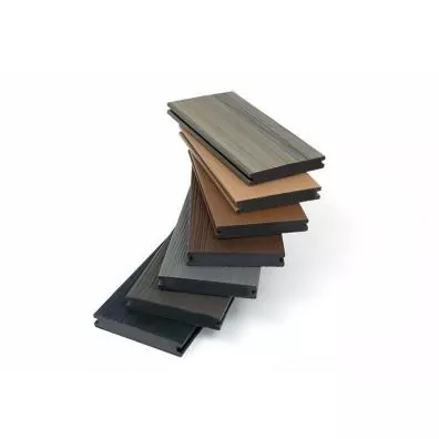
A tooling maker needs more than the letters WPC. The polymer may be PE, PP or PVC. The wood component can differ in species, particle form, size distribution and moisture condition. Formulas may also contain mineral filler, lubricant, coupling agent, pigment, stabilizer, foaming agent or recycled material.
Nanhaiya's WPC mould page identifies PE and PP with wood filler as target materials. Its product and application range also covers PVC foam board and specialized PE wood-plastic processing. Give the exact production formula so the mould is designed for the material that will enter it.
| Formula input | Why the tooling supplier needs it | What to send |
|---|---|---|
| Matrix polymer | Changes melt behavior, temperature window, drawdown and cooling response | Exact resin grade, supplier data sheet and percentage |
| Wood component | Affects feed behavior, flow resistance, moisture load and surface appearance | Wood type, flour or fiber, particle range, bulk density, moisture condition and percentage |
| Mineral filler | Changes viscosity, weight, wear and surface | Material name, particle data, treatment and percentage |
| Lubricant and processing aid | Influences die release, pressure, surface and downstream treatment | Product name, addition rate and mixing sequence |
| Coupling agent and stabilizer | Changes the compound and final product performance | Grade and percentage, plus any processing restrictions |
| Pigment or cap layer | Affects visible surface, thermal response and co-extrusion layout | Color system, layer thickness target, co-extruder position and flow ratio |
| Recycled content | Can add viscosity, contamination and moisture variation | Source, preparation, maximum percentage and lot variation |
| Foaming system | Changes density development, pressure and dimensional recovery | Complete formulation, target density and processing window |
The U.S. Department of Agriculture's Forest Products Laboratory explains that WPC moisture may be removed before processing, during a separate compounding step or in an in-line extrusion process. Its technical chapter also notes that WPC producers use different equipment routes, including precompounded pellets through a single screw, one-step twin-screw compounding and profiling, and tandem systems. The mould must be matched to the route that supplies its melt.
Reference formula rule: put one approved formula and preparation method in the tooling agreement. Future changes are possible, but the team needs a baseline when pressure, surface, dimensions or output change.
Moisture deserves its own line in the RFQ. Bubbles, pinholes and an unstable surface at the mould may begin in storage, drying, mixing, feeding or venting. A polished flow surface cannot remove water that remains in the compound.
Match the mould to the way the WPC melt is produced
A precompounded WPC pellet running through a single-screw profiler reaches the mould differently from a dry blend that is mixed and shaped in one twin-screw process. The output may have different pressure stability, temperature distribution and sensitivity to screen restriction. Ask the mould supplier to review the extruder and adapter, not only the profile.
| Production route | Typical purchasing focus | Information needed at the mould inlet |
|---|---|---|
| Precompounded pellets and single-screw profiling | Steady conveying, melting, pressure generation and profile formation | Pellet grade, moisture, screw diameter, output, melt temperature, pressure range and filtration |
| One-step twin-screw compounding and profiling | Feeding, mixing, moisture removal and forming in one continuous route | Complete formula, feeder plan, venting, screw configuration, discharge pressure, temperature and rate variation |
| Tandem extrusion | Separate compounding or drying duty from final pressure and profiling duty | Transfer method, second-extruder data, melt condition, control logic and upset handling |
| Co-extruded cap or functional layer | Stable layer distribution and adhesion around the profile | Core and cap formulas, flow ratio, inlet orientation, individual pressures and layer-thickness acceptance |
Nanhaiya supplies single screws, parallel twin screws, conical twin-screw barrels and plastic extruder machines. Choose the plasticizing section by the process job. Then design the mould around the melt condition that section can maintain.
For abrasive wood and mineral-filled formulas, review the screw and barrel wear package before increasing mould restriction. Nanhaiya's existing guide, Screw Barrel for WPC Extrusion: How to Stop Wood-Plastic Wear, covers venting, temperature and surface selection without duplicating the profile-tooling decisions in this article.
Our factory view: when a new mould raises pressure, the die is often blamed immediately. Sometimes the restriction is wrong. Sometimes the screw cannot supply a uniform, fully prepared melt at the requested rate. We compare pressure before and after changes, check the screen and material condition, and confirm the true net output before cutting the flow path again.
Profile flow must arrive together at the die exit
A WPC profile may contain thick outside walls, thin internal webs, deep grooves and small corners in one section. Each path resists flow differently. If the melt reaches one area too quickly and another too slowly, the profile can pull, twist, tear or show uneven density and surface.
The tooling design uses transition shape and local flow resistance to balance the section. The target is not identical speed at every internal point. The target is a stable profile at the exit that the calibrator can support without excessive correction.
Outer walls
Visible faces need stable supply and an appropriate surface at the die lip. Thick sections also carry more heat into the calibrator and can cool more slowly than thin features.
Internal webs
Thin ribs are vulnerable to incomplete filling or tearing. Their feed paths, junctions and downstream support should be visible in the tooling and acceptance drawings.
Grooves and corners
Small features can amplify local flow and finish problems. Mark the functional edges so tool correction protects fit instead of improving a noncritical surface.
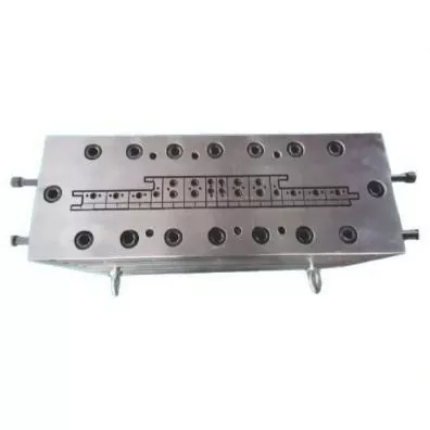
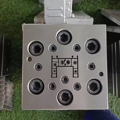
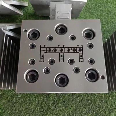
Our factory view: a mould correction should have a measured reason. We mark where the profile is heavy, thin, fast, slow or distorted, then change the responsible flow area in controlled steps. Grinding a die lip because the profile "looks wrong" can trade one defect for another and removes the record needed for the next set.
Calibration and cooling determine the cold profile
The extrusion die forms a hot section. The calibrator establishes and supports critical surfaces while heat leaves the material. Cooling continues through plates, tanks or spray sections, and the haul-off moves the profile under controlled tension. These components must share a centerline and speed reference.
Nanhaiya offers optional cooling channels in its WPC moulds. Specify the purpose of each circuit, inlet and outlet size, water quality requirement, operating temperature and available flow. The plant should also plan access for cleaning channels that may collect scale or debris.
| Downstream input | Effect on the profile | Buyer data to provide |
|---|---|---|
| Calibrator contact and support | Holds selected outside faces, grooves, edges or cavities as the section cools | Calibrator drawing, length, number of stages, vacuum method and adjustment range |
| Cooling-water condition | Changes heat-removal rate and dimensional stabilization | Supply temperature range, flow, pressure, water quality and recirculation system |
| Distance from die to calibrator | Changes unsupported hot-profile behavior before sizing | Line layout, adjustment range and start-up access |
| Haul-off type and alignment | Sets line speed and can pull the profile unevenly | Belt or track layout, speed range, contact length and center height |
| Cutting and stacking | Can reveal or create movement after primary cooling | Cut length, saw or cutter type, support table and stacking method |
Do not promise cold dimensions at the die exit. Agree where and when each dimension will be measured after cooling. Use the same conditioning and measuring method for approval samples and production control.
The USDA Forest Products Laboratory's profile-extrusion research describes a process in which the molten WPC was shaped through a die, followed by a sizing die, water spray tank and puller. That sequence is a useful reminder: the forming result belongs to the whole line, even when the mould is purchased as one item.
Specify mould construction, treatment and inspection
Nanhaiya manufactures its WPC moulds from steel and describes high-strength alloy steel with hardened and polished surfaces for the working areas. Each mould is CNC machined, heat treated and polished. The final agreement should turn those general product attributes into component-level requirements.
- Material grade for each main component
- Heat-treatment and hardening scope
- Finished hardness requirement and test location
- Flow-surface finish requirement
- Critical dimensions and tolerances
- Registers, dowels and assembly references
- Heater quantity, power, voltage and connectors
- Thermocouple type, location and cable details
- Pressure and melt-temperature ports
- Cooling-channel drawing and pressure test
- Fastener material, grade and spare quantity
- Replaceable insert and wear-part definition
- Rust protection, packing and storage method
- Material, treatment and dimensional records
Do not request the hardest possible surface everywhere. The die body, inserts, fasteners, adapter and support have different jobs. The specification should combine surface condition, substrate strength, repair method and corrosion exposure with the expected wood and mineral content.
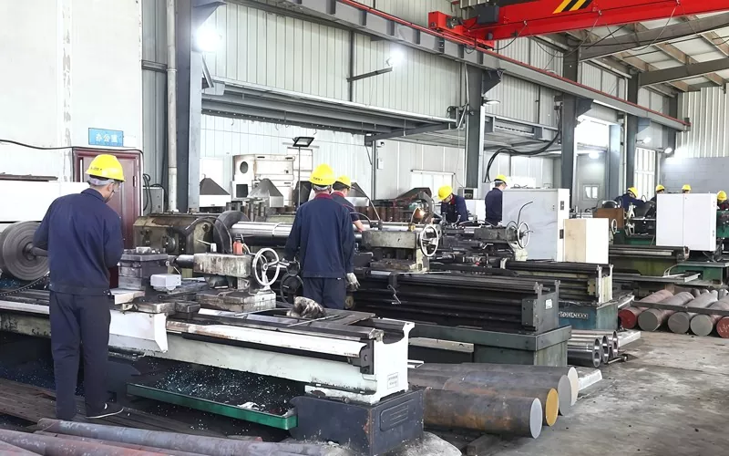
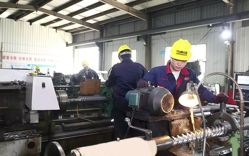
Supplier qualification can include Nanhaiya's production equipment, certificate information and installation and maintenance support. Put required documents and support in the purchase order rather than relying on a general catalog statement.
Use the defect pattern to find the responsible zone
WPC profile defects can begin in the raw material, mixer, feeder, screw and barrel, mould, calibrator, cooling section or haul-off. The location of a defect on the cross-section and its change over time give useful clues. Record them before changing temperature, speed and tooling together.
| Observed defect | Mould checks | Other line checks | Procurement lesson |
|---|---|---|---|
| Profile twists in one repeatable direction | Flow balance, wall compensation, die alignment and discharge condition | Calibrator position, cooling balance and haul-off alignment | Make twist a measured acceptance item after full cooling |
| One wall or rib is thin | Local restriction, insert position, deposit, wear or damaged flow surface | Formula consistency, moisture, screen condition and output stability | Mark every critical wall and rib on the drawing |
| Internal web breaks | Web feed path, junction design and exit support | Moisture, contamination, melt preparation, speed and unsupported distance | Include a cross-section cut inspection in the run test |
| Rough or torn surface | Die-lip finish, deposit, temperature and local flow | Formula, lubricant balance, moisture, dispersion and line speed | Approve a physical surface sample under a named formula |
| Bubbles or pinholes | Hold-up zones and local overheating | Wood moisture, drying, feeding, venting and volatile removal | Record moisture preparation and vent performance in the test plan |
| Brown or black marks | Dead zones, deposits, excessive local temperature and cleaning damage | Barrel deposits, thermal history, shutdown practice and contaminated feed | Ask for a documented start-up, shutdown and cleaning procedure |
| Dimensions drift during a run | Thermal movement, loose adjustment, wear and cooling-channel condition | Output, temperature, pressure, vacuum, water and haul-off speed | Use timed sampling through a stable run, not one early sample |
| High pressure and low output | Restricted flow, blocked path, unsuitable transition or low die temperature | Screen blockage, worn screw, feed limitation and material viscosity | Define pressure location and a usable operating window |
Practical diagnostic method: mark top, bottom, left and right on the extrudate and final profile. Record the same orientation through the calibrator. If the defect rotates or changes after a line component, the investigation has a better starting point than a general instruction to adjust the mould.
Our factory view: we are cautious when a defect is described only as "the surface is bad." We ask where it appears, whether it is continuous, when it begins after start-up, which formula lot is running and what happens to pressure. A close photo with orientation and a retained section often saves more time than a long message.
WPC extrusion mould RFQ checklist
A complete RFQ makes quotations comparable and gives the engineering team a clear reference condition. Use one revision number across the product drawing, formula, line layout and acceptance document.
- Identify the finished product. State decking, fencing, door frame, ceiling, panel, trim or another profile. Explain the application and which surfaces are visible or functional.
- Attach the controlled cross-section. Include dimensions, walls, ribs, cavities, radii, datums, tolerances, straightness, twist and target mass per length.
- Provide the complete formula. List polymer grade, wood type and content, mineral filler, lubricant, coupling agent, stabilizer, pigment, recycled content and any foaming or cap-layer system.
- Describe material preparation. Give drying, mixing, compounding, pelletizing, storage, bulk-density and moisture-control information.
- Define the extrusion route. State single screw, parallel twin, conical twin or tandem; screw diameter; output; line speed; filtration; normal pressure; and temperature window.
- Control the mechanical interface. Attach the flange, register, bolt circle, melt inlet, sealing face, center height, support, lifting and space envelope.
- List electrical and utility data. Give voltage, frequency, heater control, thermocouple type, cable standard, cooling-water temperature, flow, pressure and quality.
- Show the downstream layout. Include calibrator sections, vacuum or water connections, cooling tanks, support tables, haul-off, embossing unit, cutter and available adjustment.
- Define surface work. State whether the product leaves the line smooth, embossed, sanded or brushed and how much material the secondary process removes.
- List every supplied component. Separate adapter, die body, inserts, calibrators, cooling plates, heaters, sensors, seals, fasteners, stands, tools and spares.
- Request the technical file. Include drawings, bill of materials, material and treatment records, inspection report, electrical list, cooling diagram, manual and spare-parts list.
- Write the acceptance test. Name the formula, profile, output, speed, run duration, process records, sampling frequency, dimensional limits, surface sample and finished-product tests.
Replacement warning: do not use a worn mould as the only definition of the new set. Combine original drawings, machine-interface measurements, a good retained profile and the reason for replacement. Copying worn flow features can reproduce the old defect.
For a PVC or WPC board line, review the PVC board conical twin-screw barrel with the tooling package. For high-output or compounding duties, compare the co-rotating parallel twin-screw barrel and the broader parallel twin-screw range. These links support equipment selection; the final choice still depends on the formula and process route.
Accept the mould with a controlled production run
Start with component inspection, then prove the forming result on the line. The agreed WPC formula matters because a different polymer, wood content, moisture condition or lubricant system can change pressure, surface and dimensional recovery.
| Acceptance stage | What to verify | Record to retain |
|---|---|---|
| Document review | Drawing revisions, component list, material and treatment scope, heaters, sensors, cooling circuits, spares and manuals | Signed document register |
| Bench inspection | Critical interfaces, registers, openings, inserts, sealing faces, fasteners, flow surfaces and assembly orientation | Dimensional and visual report tied to part numbers |
| Installation | Center height, flange fit, support, lifting access, heater wiring, sensors, water connections and alignment to calibrators | Installation checklist and photographs |
| Heat-up | Zone identification, controller response, sensor reading, current draw, leakage and cooling-channel condition | Zone map and stabilized readings |
| Production run | Approved formula, feed preparation, output, line speed, temperatures, pressure, motor load, cooling and haul-off conditions | Time-based process sheet and retained raw-material sample |
| Profile inspection | Outside dimensions, wall and rib sections, straightness, twist, surface, color, mass per length and fit with mating components | Measurements tied to cut position and production time |
| Change and recovery | Agreed adjustment, normal stop and restart, or one size or color change when it matters to daily production | Operator sign-off and remaining-action list |
The finished product may need tests that go far beyond profile dimensions. ASTM D7031 is a guide for evaluating mechanical and physical properties of WPC products, and it states that users should select the tests appropriate to the application. ASTM D7032-21 covers performance ratings for WPC and plastic-lumber deck boards, stair treads, guards and handrails.
For natural fibre-reinforced composite deck boards, ISO 16616:2015 provides test methods, while ISO 19821:2017 addresses span rating. Confirm the applicable edition, national code and product scope before writing the contract. The mould does not carry the finished product's compliance.
Our factory view: the best handover is a stable process window and a set of traceable samples. We want to know which formula ran, how fast the line moved, where pressure settled, how cooling was set and when each sample was cut. One good-looking board placed on a table does not explain whether the line can repeat it.
Frequently asked questions
What information is required to quote a WPC extrusion mould?
Send the final profile drawing with tolerances, the complete WPC formula, material preparation method, extruder and adapter details, target output and line speed, cooling and haul-off layout, surface requirements, changeover plan, available utilities and a measurable acceptance test. A physical product sample is useful, but it should not replace the controlled drawing.
Can one WPC mould run PE, PP and PVC-based wood composites?
The same finished shape does not make the materials interchangeable. PE, PP and PVC-based WPC formulations can differ in flow, temperature window, lubrication, drawdown and cooling response. We review the exact formula and processing route before deciding whether one tooling body and separate inserts are practical or whether dedicated tooling is safer.
Does a WPC extrusion mould include the calibrator?
The quoted scope must say. The extrusion die shapes the hot melt, while the calibrator, cooling sections and haul-off hold and stabilize the profile as it cools. Ask for a line-item tooling list that identifies the die, adapters, calibrators, cooling plates, seals, heaters, sensors and change parts.
Why does the WPC profile twist or bow after the mould?
Twist or bow can come from uneven die flow, unbalanced wall or web sections, unequal cooling, calibrator alignment, unstable output, nonuniform temperature or a misaligned haul-off. Measure the direction and timing of the distortion before adjusting several variables. The complete forming and cooling system must be checked.
Which material does Nanhaiya use for WPC moulds?
Nanhaiya's WPC mould page lists steel and describes high-strength alloy steel with hardened and polished surfaces. Each mould is CNC machined and heat treated, with optional cooling channels. The approved quotation should identify the exact grade, treatment scope, flow-surface finish and inspection records for the project.
How should a hollow WPC decking profile be specified?
Provide the complete cross-section with outer dimensions, wall and rib thicknesses, cavity geometry, radii, critical tolerances, visible faces, embossing or sanding allowance, target mass per length and the final product test standard. Mark which dimensions are functional so the tooling maker knows where adjustment is most important.
Can the mould guarantee WPC decking standard compliance?
No. The mould controls profile formation, but final product performance also depends on the formula, compounding, moisture control, extrusion conditions, cooling and production quality system. The manufacturer must test the finished decking to the applicable requirements, such as the selected ASTM, ISO or national standard.
How should a WPC extrusion mould be accepted?
Inspect the approved drawings, materials, treatment, interfaces, heaters, sensors, flow surfaces and change parts first. Then run the agreed production formula at a named profile, output and line speed. Record process conditions and measure the cooled profile's dimensions, wall and rib sections, straightness, twist, surface, mass per length and any tests required by the product specification.
Technical content prepared from Nanhaiya's current WPC mould, screw-barrel, equipment and service pages. External technical support is limited to official USDA, ASTM and ISO sources. Final tooling dimensions, materials, treatment, line scope and acceptance criteria are controlled by the approved project documents.