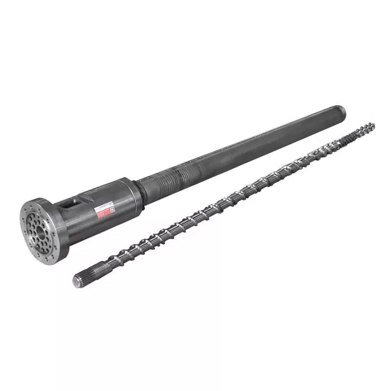

What the Screw Barrel Actually Does
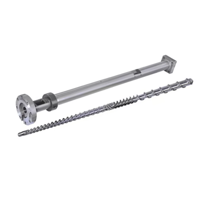
The screw and barrel work as a matched pair. Here's the sequence every cycle:
- Feeding — Plastic pellets drop from the hopper into the feed zone.
- Melting — The rotating screw generates shear heat. Combined with barrel heaters, pellets melt and compress.
- Metering — The melt becomes uniform in temperature and pressure before injection.
- Injection — The screw moves forward like a plunger, pushing molten plastic into the mold.
Every design variable — geometry, zone proportions, surface treatment — affects how well those four steps happen. A mismatch in any one of them shows up as a production problem.
Decision 1: L/D Ratio
The L/D ratio (screw flighted length divided by its diameter) is the most important number on the spec sheet. It controls residence time, mixing quality, and heat distribution. Most general-purpose injection molding applications use 20:1.
| Resin | Recommended L/D |
|---|---|
| PP, PE, PS (standard) | 18:1 – 20:1 |
| ABS, PC | 20:1 – 24:1 |
| PVC (heat-sensitive) | 16:1 – 20:1 |
| PET | 20:1 – 22:1 |
| Nylon (PA) | 18:1 – 20:1 |
| GF-reinforced materials | 20:1 – 24:1 |
Decision 2: Compression Ratio
The compression ratio (CR) measures how much the screw channel narrows from the feed zone to the metering zone. Higher CR compresses the melt more aggressively — good for amorphous resins that soften gradually. Lower CR is gentler, which is what you need for heat-sensitive or fiber-filled materials.
| Resin | Compression Ratio |
|---|---|
| ABS, PC, PMMA (amorphous) | 3.0 – 3.5:1 |
| PP, PE, Nylon (semi-crystalline) | 2.5 – 3.0:1 |
| PVC | 2.0 – 2.5:1 |
| PET | 2.3 – 2.6:1 |
| GF-reinforced (≥15%) | 2.0 – 2.5:1 |
Decision 3: Zone Proportions
A standard injection screw divides into three zones. The proportion of each zone matters as much as the total L/D.
- Feed Zone (L1): Deep channels that accept solid pellets from the hopper. Longer = more throughput capacity.
- Compression Zone (L2): Channel depth decreases progressively. Most of the melting happens here.
- Metering Zone (L3): Shallow, consistent channels. Ensures uniform melt temperature and pressure before injection.
| Resin | Feed (L1) | Compression (L2) | Metering (L3) |
|---|---|---|---|
| PP / PE | 50% | 25% | 25% |
| ABS / PC | 40% | 40% | 20% |
| PET | 40% | 40% | 20% |
| Nylon (PA) | 35–45% | 35–40% | 20–25% |
| PVC | 35% | 50% | 15% |
Decision 4: Screw Barrel Material
38CrMoALA — The Standard Baseline
Nanhaiya's injection molding screws are manufactured from 38CrMoALA alloy steel, heat-treated and quenched. This base material handles standard thermoplastics like PE, PP, PS, and ABS well, with a service life of approximately 10,000–20,000 hours under normal operating conditions.
Nitriding
Gas nitriding at 500–560°C forms a nitrided layer 0.5–0.8mm thick with a hardness of 950–1050 HV (~62 HRC). This improves wear resistance by 30–40% compared to untreated steel. Standard for most injection molding applications running unfilled or lightly filled materials.
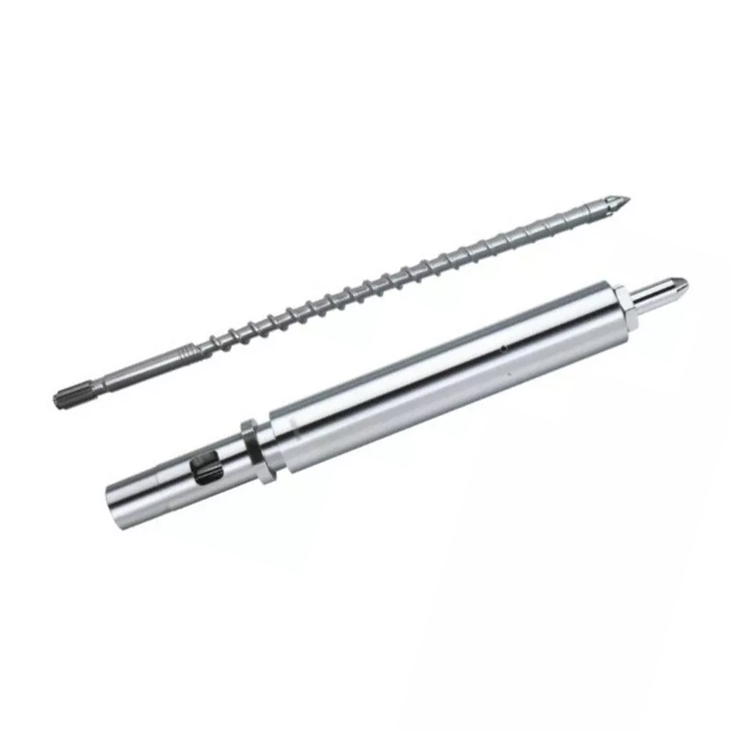
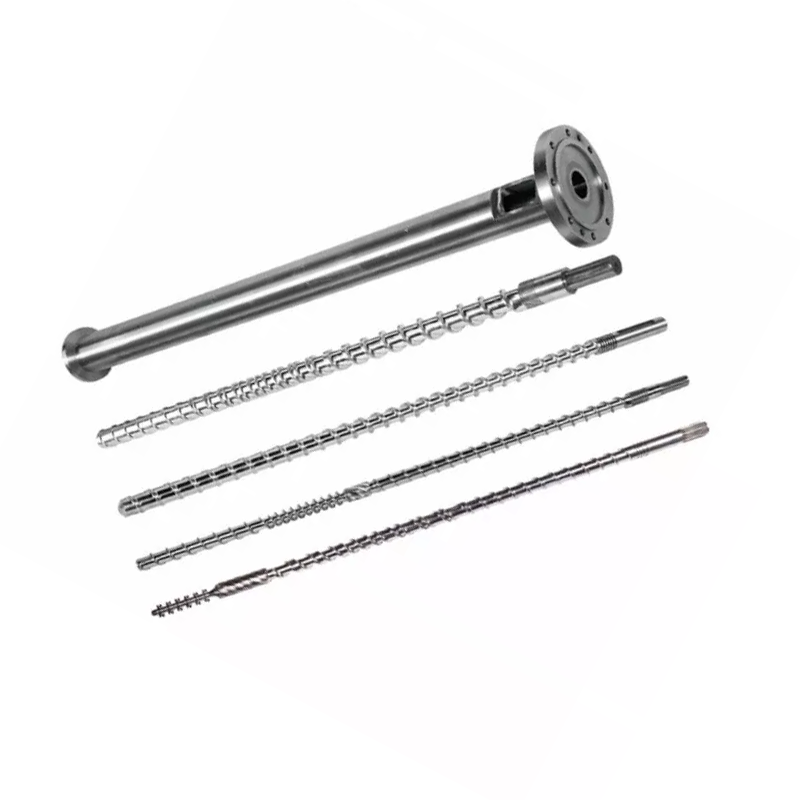
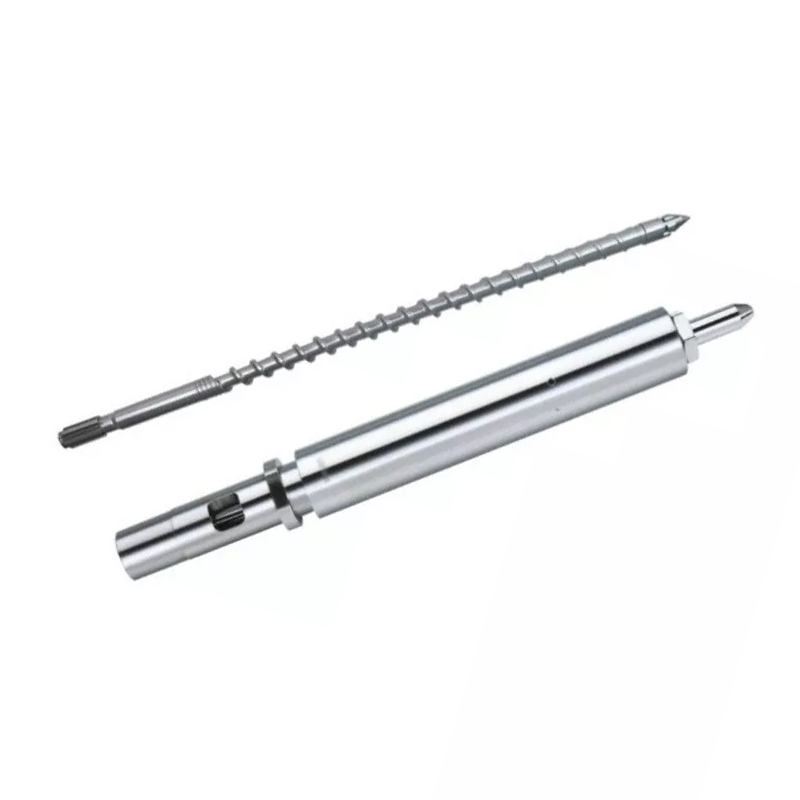
Nanhaiya mutant (abrupt) injection molding screw — suited for crystalline resins like PP, PE, and Nylon.
Bimetallic — For Abrasive Applications
Bimetallic barrels have a high-alloy wear-resistant lining metallurgically bonded to the barrel bore. Nanhaiya's bimetallic process achieves an inner bore hardness of 62 HRC through hard alloy spray welding around the high-wear areas of the barrel interior.
| Application | Screw Material | Barrel Treatment |
|---|---|---|
| PE, PP, PS (unfilled) | 38CrMoALA nitrided | Standard nitrided |
| ABS, PC, Nylon (unfilled) | 38CrMoALA nitrided | Standard nitrided |
| PA + GF ≤30% | 38CrMoALA, quenched + tempered | Nitrided or bimetallic |
| GF content 15–50% | Bimetallic / TC flight edges | Bimetallic |
| PVC / corrosive resins | Corrosion-resistant alloy | Bimetallic (CR grade) |
| Carbon fiber filled | Tungsten carbide | TC-sprayed bore |
Decision 5: Screw Diameter and Shot Size
Your actual shot should fall between 35% and 70% of the screw's maximum shot capacity. Below 35%, material sits in the barrel too long and risks degradation. Above 70%, the screw can't recover fast enough within the cycle.
Below are common configurations available from Nanhaiya:
| Injection Amount (g) | Screw Ø × Length (mm) | Barrel Ø × Length (mm) |
|---|---|---|
| 30–90 | Φ30×900 | Φ85×860 |
| 60–125 | Φ35×910 | Φ85×860 |
| 100–150 | Φ38×935 | Φ95×900 |
| 125–300 | Φ42×1030 | Φ105×1110 |
| 250–400 | Φ45×1210 | Φ115×1165 |
| 300–500 | Φ50×1300 | Φ125×1260 |
| 500–700 | Φ60×1380 | Φ140×1350 |
| 700–1000 | Φ70×1790 | Φ160×1685 |
| 1000–1500 | Φ160×3500 | Φ270×3200 |
| 1300–2500 | Φ170×3415 | Φ317×3380 |
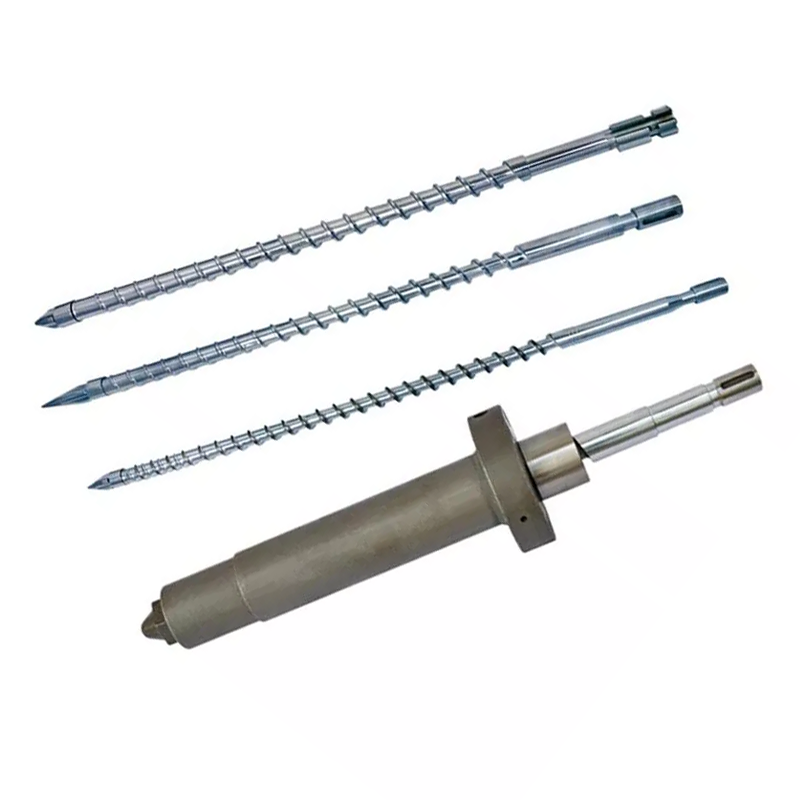
Nanhaiya gradual injection molding screw — better for amorphous resins like ABS, PC, and PMMA.
Warning Signs Your Current Screw Is Wrong for the Job
- Black specks or burn marks — Material degrading from excessive residence time or a hot spot. Check barrel temperature zones and screw clearance.
- Inconsistent shot weight — Often a worn non-return valve or excessive screw-to-barrel clearance allowing backflow.
- Splay marks on the surface — Moisture or gas in the melt. May indicate inadequate pre-drying or a screw geometry that isn't venting properly.
- Slow recovery / long cycle time — Plasticizing capacity is insufficient. Screw diameter likely needs to increase.
- High scrap on color changes — Poor mixing in the metering zone. A Maddock or barrier mixing element added to the screw often solves this.
What to Tell Your Manufacturer When Requesting a Quote
- Machine brand and model — or bore diameter and flange dimensions for non-standard machines
- Primary resin(s) — include filler type and percentage if applicable
- Shot size range — minimum and maximum in grams
- Target cycle time
- Current problems you're trying to solve — if any
Get a Technical Recommendation from Nanhaiya
We respond within 12 hours. Our engineering team can specify the right screw geometry, material grade, and dimensions for your machine and resin — before you commit to a quote.