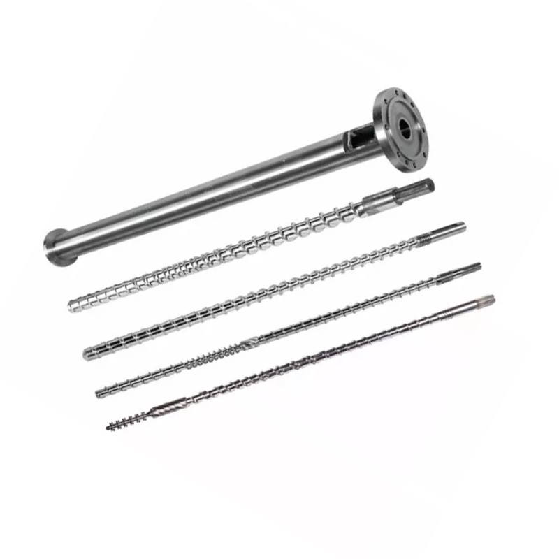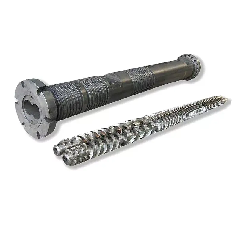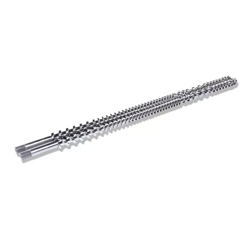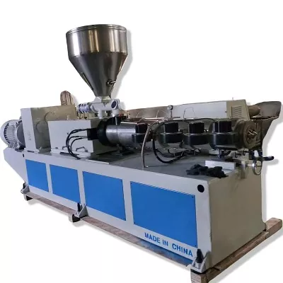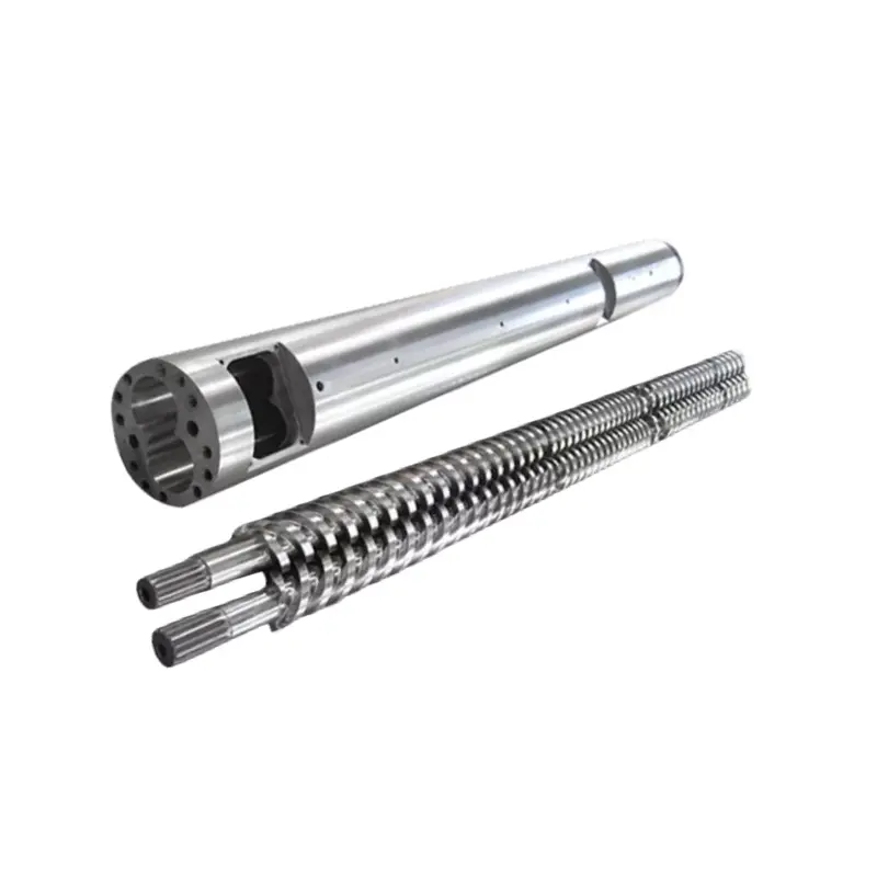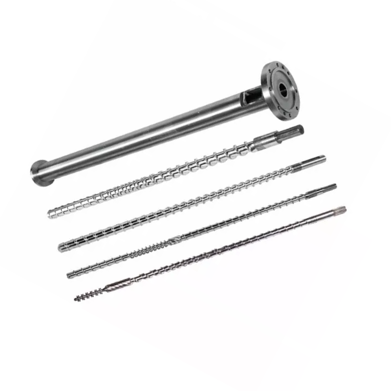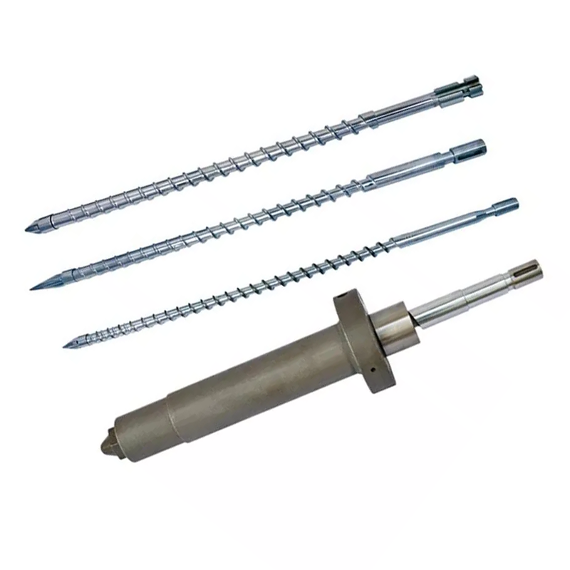

A screw should be selected around the actual resin grade, blend, film product and extrusion line. “65 mm screw for LDPE film” is a starting point, not a complete specification.

Quick answer
Choose a film-blowing screw in this order: resin and formulation, finished film and layer structure, line duty, then screw geometry and surface system. Ask for the exact resin grade and melt flow test condition, not only “LDPE,” “LLDPE” or “HDPE.” Record the blend ratio, additives, recycled content, output, screw speed, motor, die, film width and thickness range. Only then decide diameter, L/D, feed depth, melting profile, metering section and whether a barrier or mixing section is justified.
Why “65 mm screw for LDPE film” is not enough
We receive inquiries that give a diameter, a polymer acronym and little else. That is enough to identify the product family, but not enough to cut the flights. Two lines can both make polyethylene film with a 65 mm screw while running different resin grades, blends, speed ranges, dies and output targets. A geometry that works on one line can run hot, surge or leave unmelt on the other.
Film blowing makes the specification more sensitive because extrusion is only the first part of the process. Melt consistency reaches the die, bubble, air ring and take-up system. Thickness variation or poor optical appearance may begin at the screw, but it may also come from feeding, heater control, a blocked screen, die condition, cooling or haul-off instability. Copying the screw before separating these causes can reproduce the same problem in new steel.
Our factory view: when an inquiry says only “65 mm screw for LDPE film,” we stop at the drawing stage and ask for the resin data sheet, blend ratio, layer, output, screw speed, motor power, film dimensions and present symptom. This is not paperwork for its own sake. Those answers decide whether the original geometry should be reproduced, corrected or replaced with a different melting strategy.
What Nanhaiya publishes for its single-screw range
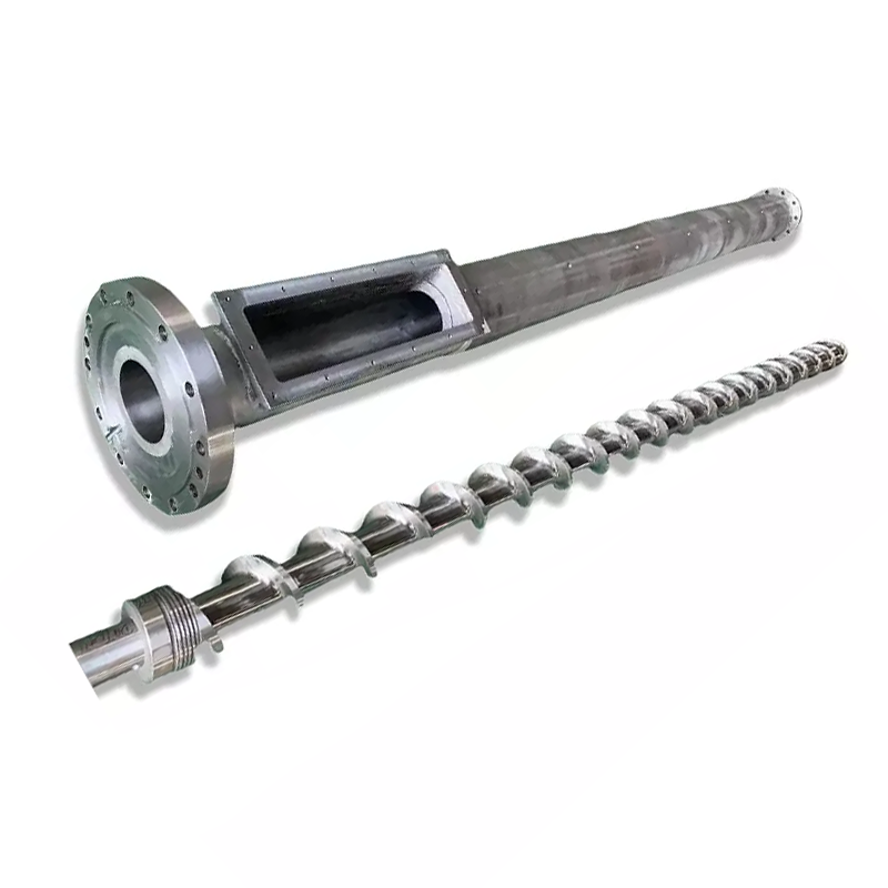
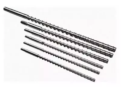
Nanhaiya's film single-screw page lists standard diameters of 30, 35, 40, 45, 50, 55, 60, 65, 70, 80, 90, 100, 120 and 150 mm. It gives 25:1, 28:1, 30:1, 33:1 and 35:1 as L/D references and lists LDPE, LLDPE, HDPE, PP and PVC among the applicable materials. It also describes use on three-layer coextrusion film lines.
The broader single-screw category page publishes the family-level references below. They help a buyer identify an approximate model range. They are not a promise that every combination of output, speed, motor and length applies to a particular film formulation.
| Model | L/D | Published capacity | Screw speed | Motor power | Center height |
|---|---|---|---|---|---|
| NHY20 | 20:1 | 3 to 5 kg/h | 10 to 60 rpm | 1.1 / 1.5 / 2.2 kW | 1000 to 1400 mm |
| NHYZS25 | 25:1 | 5 to 8 kg/h | 10 to 60 rpm | 2.2 / 3.0 / 4.0 kW | 1000 to 1400 mm |
| NHY30 | 25:1 | 5 to 10 kg/h | 10 to 60 rpm | 2.2 / 3.0 / 4.0 kW | 1000 to 1400 mm |
| NHY45 | 25:1 to 36:1 | 10 to 120 kg/h | 10 to 150 rpm | 5.5 to 22 kW | 1000 to 1400 mm |
| NHY65 | 25:1 to 36:1 | 60 to 300 kg/h | 20 to 150 rpm | 22 to 75 kW | 1000 mm |
| NHY75 | 25:1 to 36:1 | 200 to 450 kg/h | 20 to 150 rpm | 30 to 132 kW | 1000 mm |
| NHY90 | 25:1 to 36:1 | 180 to 600 kg/h | 20 to 110 rpm | 30 to 185 kW | 1000 to 1100 mm |
| NHY120 | 25:1 to 36:1 | 320 to 1000 kg/h | 20 to 90 rpm | 75 to 280 kW | 1000 to 1250 mm |
| NHY150 | 25:1 to 36:1 | 400 to 1300 kg/h | 20 to 75 rpm | 90 to 400 kW | 1000 to 1300 mm |
Source: Nanhaiya single-screw category page, checked August 24, 2026. Capacity is application-dependent. Confirm the project specification on an approved drawing and quotation.
About the published tungsten statement: the film-screw page states that the screw and flange can receive three-sided tungsten-alloy treatment and gives a three-times wear-resistance statement. We treat this as a product-page reference, not a service-life calculation. A purchase order should identify the treated area, alloy system, required inspection evidence and acceptance criteria. Feedstock, contamination, clearance and operating conditions still affect wear.
Start with the actual resin, not the polymer acronym
“LDPE” does not describe one fixed processing behavior. Grade, molecular architecture, melt flow, density, additives and blend composition matter. Peer-reviewed work on LLDPE, LDPE and their blends found that the parent polymers and blend composition influence shear and elongational rheology, which in turn matters in film blowing. That is why we ask for the supplier, grade and formulation rather than choosing from the three-letter resin name alone.
Record melt flow with its test condition
Melt flow rate is useful, but the number needs its test condition and it does not summarize the whole resin. The current ASTM D1238-26 method covers melt flow testing by extrusion plastometer. ASTM notes that flow-rate data can help with quality control and uniformity, while other properties require their own valid correlation. In practical terms: send the value, test temperature and load, then add the grade data sheet. Do not select a screw from MFR alone.
Describe the complete formulation
- Virgin-resin supplier and exact grade
- LDPE, LLDPE and HDPE blend percentages
- Masterbatch, slip, antiblock, processing aid and filler levels
- Recycled-content percentage, source, form and variability
- Pellet bulk density, contamination and moisture concerns
If the factory is expected to run several formulations, name the normal recipe, the most difficult recipe and how often changeovers occur. A design optimized for one stable grade is a different project from a screw expected to tolerate a broad operating window.
Define the film product and every layer
Nanhaiya's product page lists bags, cling film, agricultural mulch film, packaging film, liquid-packaging film, shrink and stretch film, static-protection film, pond liner film and heavy-duty packaging among the intended applications. These products do not impose identical priorities. One buyer may focus on optical consistency and thin-gauge stability. Another may prioritize output, toughness or the ability to process a variable recycled blend.
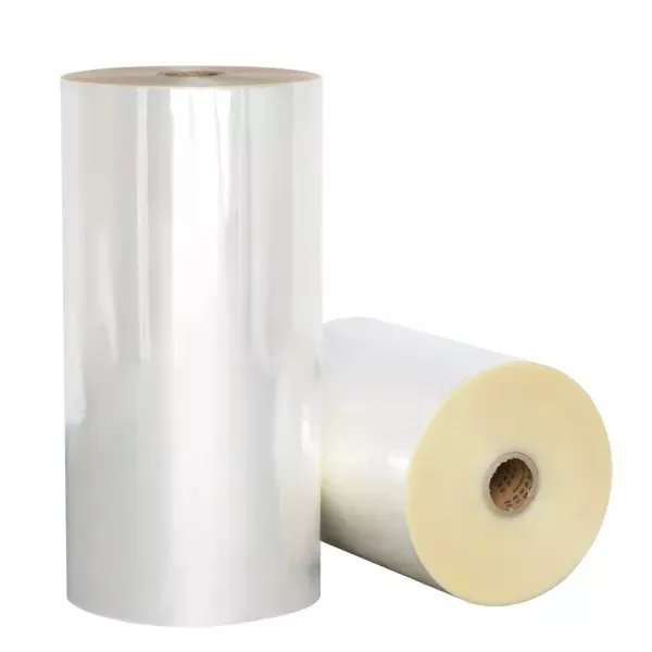
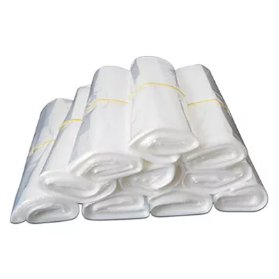
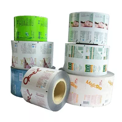
For a mono-layer line, provide the complete formulation and operating window. For an ABA or ABC line, define each extruder separately. The skin and core layers can use different materials, recycled content and output shares. We do not assume that one geometry should be copied into all three barrels merely because the screw diameters match.
Our factory view: barrier and mixing sections are tools, not status symbols. If a mono-layer line runs one proven resin recipe at modest output, a well-matched conventional screw may be the safer and more economical choice. We recommend more complex geometry only when the material range or a defined melting and mixing problem justifies it.
Translate the application into screw geometry
Once the resin, film and machine duty are clear, the screw can be divided into decisions that an engineer can review on a drawing.
- Confirm the envelope. Record nominal diameter, effective flighted length, overall length, drive-end connection, tip and die-side connection, barrel bore and available center height.
- Set the feed duty. Pellet form, bulk density, recycled flake and hopper or force-feeding arrangement affect how consistently material enters the flights.
- Set the melting profile. Feed depth, compression transition and channel development must suit the formulation and the available heated length.
- Set metering and homogenization. The design must deliver stable melt to the screen and die without adding a mixing section that consumes unnecessary pressure or heat.
- Choose the material and surface system. Match base steel, nitriding or bimetallic protection, and any hardfacing to the wear and corrosion mechanism.
- Approve tolerances as a pair. Screw dimensions and barrel bore must be reviewed together. A new screw working in a worn barrel can leave excessive clearance.
For a deeper comparison of melting concepts, see barrier vs conventional vs mixing screw geometry. For a replacement project, use the measurement fields in our replacement single-screw specification guide.
Match common film-blowing conditions to the right decision
| Production condition | What we would verify first | Design direction to evaluate | What not to assume |
|---|---|---|---|
| Stable mono-layer film with one proven grade | Existing output, melt temperature, motor load and current geometry | Preserve a simple, proven process window where possible | A barrier section is automatically better |
| LLDPE-rich blend or difficult melting complaint | Exact grades, blend ratio, rpm, heater profile, pressure and unmelt evidence | Review melting length, barrier concept or controlled mixing | More compression alone will solve it |
| High recycled content | Flake or pellet form, bulk density, contamination, moisture and recipe variability | Review feeding stability, wear zones, filtration and operating window | Harder steel corrects inconsistent material |
| Thin film at higher output | Specific output, melt temperature, pressure stability, drive margin and cooling limit | Balance throughput with melt uniformity and residence time | The largest published kg/h value applies to this grade |
| Three-layer coextrusion | Recipe and output share of every layer | Specify each extruder and layer independently | Matching diameters require matching geometry |
| Thickness variation or bubble instability | Feeding, heaters and sensors, screen, die, air ring and take-up | Change the screw only after the source is isolated | Every film defect begins in the screw |
Our factory view: when a buyer reports thickness variation, we do not immediately offer a “better” screw. We first ask whether the output and motor load fluctuate, whether the melt pressure is stable, and what happens at the die and air ring. If the evidence points outside the screw and barrel, changing geometry may spend the budget without removing the cause.
For replacement projects, inspect the barrel before copying the screw
A worn sample can preserve the drive connection and overall arrangement, but it does not reliably preserve the original flight diameter or clearance. Measure the barrel bore along its working length and record the screw flight diameters by zone. Also document where wear, scoring, corrosion or material buildup is concentrated.
If the barrel is worn beyond the intended clearance, a new screw alone can still run with excessive leakage. Review our guides on measuring screw and barrel wear and deciding whether to replace the screw only or the matched pair.
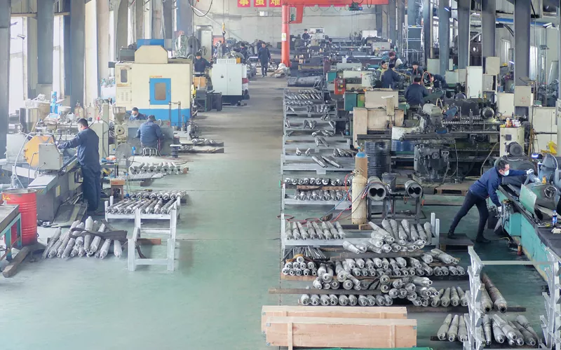
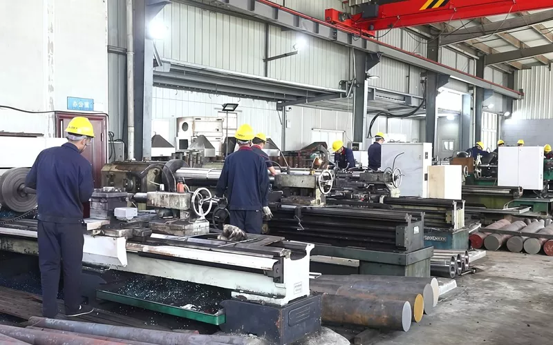
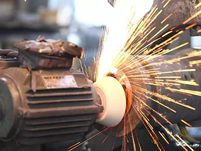
Nanhaiya's equipment page also publishes 0.02 mm drilling and milling positioning accuracy and describes continuous drilling, reaming and chamfering to reduce reclamping error. It states that five-axis machining is used for irregular flights and special flanges. These are factory capability references. The dimensions and inspection points that control an individual order must still appear on the approved drawing.
Film-blowing single-screw RFQ checklist
A useful quotation begins with evidence. Send as many of the following fields as possible:
- Resin manufacturer and exact grade
- MFR or MVR value with temperature and load
- Blend percentages and masterbatch levels
- Recycled content, form and source variability
- Mono-layer, ABA or ABC structure
- Material and output share for each layer
- Film type, layflat width and thickness range
- Normal and maximum output targets
- Screw diameter, L/D and overall length
- Motor power, gearbox ratio and rpm range
- Barrel-bore measurements and heater layout
- Screen changer, die and cooling information
- Dimensioned drawing of both end connections
- Photos and measurements of the worn parts
- Current melt pressure, temperature and load
- A precise description of the production problem
If some fields are unavailable, state that clearly. A known gap can be managed. A guessed value can enter the drawing and become an expensive machining error.
Frequently asked questions
Do LDPE, LLDPE and HDPE need different film-blowing screws?
They can. Polymer family alone is not enough to specify the difference. The exact resin grade, melt flow rate and test condition, density, blend ratio, additives, recycled content, output target and film structure all affect the design decision.
What information should I send for a film-blowing screw quotation?
Send the resin supplier and grade, formulation and blend percentages, film type, width and thickness range, target output, mono-layer or coextrusion structure, screw diameter and L/D, motor power, screw-speed range, drawings, and a clear description of the current production problem.
Is a barrier or mixing screw always better for blown film?
No. A stable mono-layer line running a narrow range of known materials may not need more complex geometry. Barrier or mixing sections should solve a defined melting or homogenization problem, not be added as a sales upgrade.
What L/D ratio should a film-blowing screw use?
Nanhaiya's film-screw page lists 25:1, 28:1, 30:1, 33:1 and 35:1 as reference options. The correct choice still depends on the resin, output, available drive, barrel heating, machine layout and required melt quality.
Can one screw handle virgin and recycled polyethylene film materials?
Possibly, but the recycled stream must be described. Variability, contamination, fillers, moisture and bulk density can alter feeding, wear and melt stability. A harder surface alone does not correct inconsistent feedstock.
Can the same screw specification be copied across all layers of a three-layer blown-film line?
Not automatically. Each extruder may run a different formulation, output share and function. Specify the A, B and C layers separately before deciding whether any geometry can be shared.
Send Nanhaiya your film application
Nanhaiya was established in 2014 and provides custom screw design, alloy spray welding and screw manufacturing in Zhoushan, Zhejiang, China.
Email: info@nhyscrew.com
Phone: +86-13505809643
Mobile / WhatsApp: +86-13587082002
Address: Block C, No. 2 West Section, Xingzhou Avenue, Dinghai District, Zhoushan City, Zhejiang Province, China
Sources checked
- Nanhaiya, LDPE and HDPE film single screw. Product range, application and hosted images.
- Nanhaiya, single screw category. Published family-level model table, materials and applications.
- Nanhaiya, production equipment. Published machining capabilities and factory images.
- Nanhaiya, about us. Company history and manufacturing scope.
- ASTM D1238-26. Standard test method and stated significance of melt-flow-rate data.
- Yamaguchi, M. et al., “Rheology of LLDPE, LDPE and LLDPE/LDPE blends and its relevance to the film blowing process”, Polymer International, 2000.
Technical note: published website ranges are selection references. Final geometry, material, treatment, tolerances, inspection and commercial terms are controlled by the approved drawing, quotation and purchase contract.