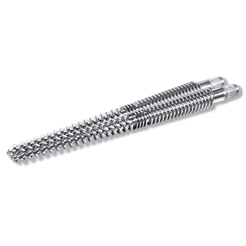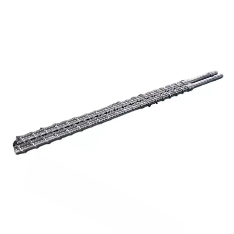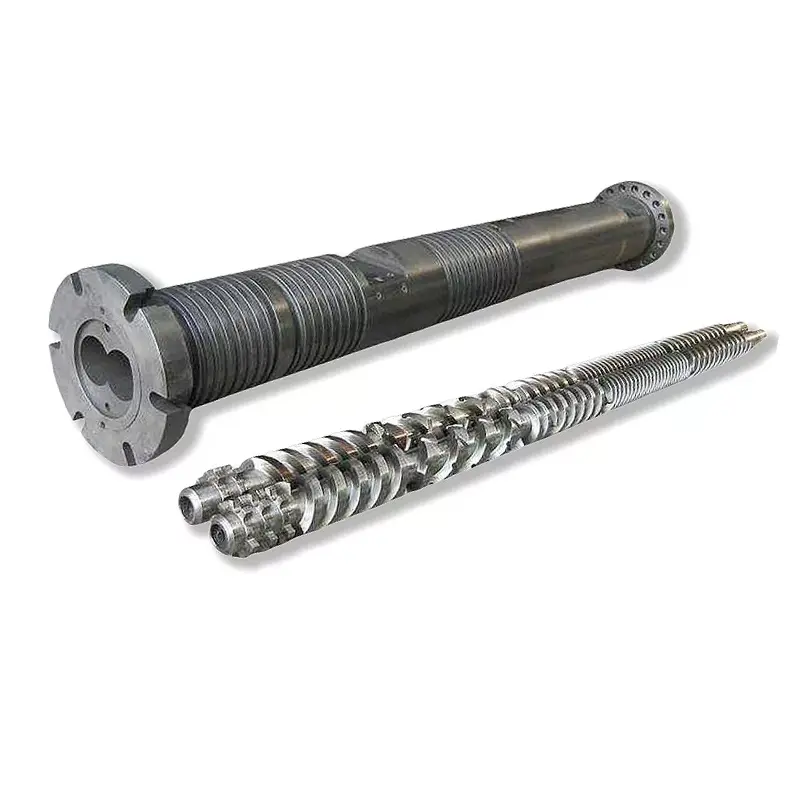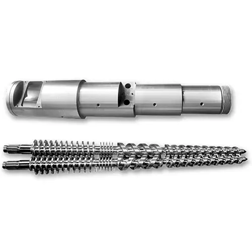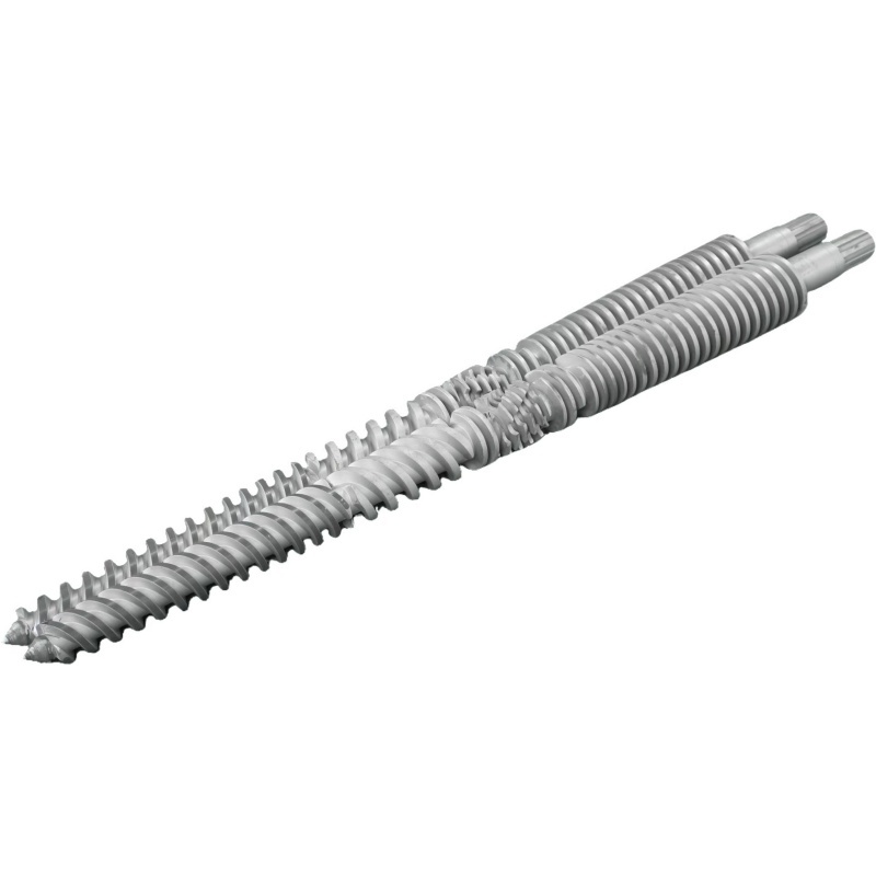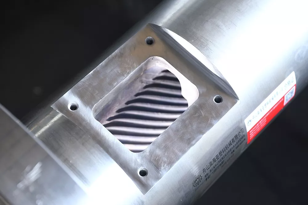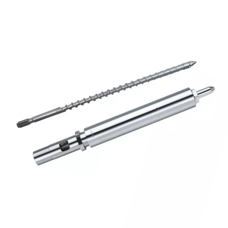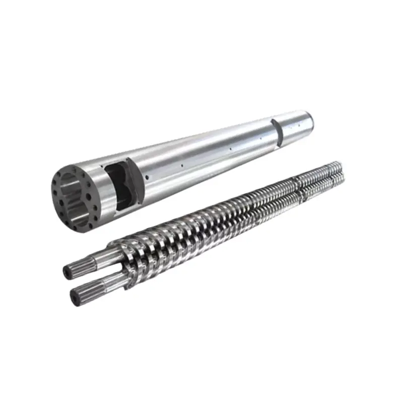

A worn screw sample tells us where metal remains. It does not tell us the original diameter, the barrel condition or the working clearance by itself. We need a matched measurement map before we decide what to copy, repair or replace.

Quick answer
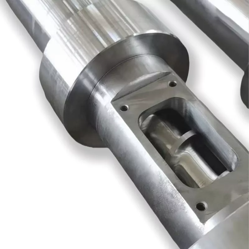
Measure wear as a location-based pair, not as one screw diameter. Mark axial stations through the feed, compression and metering zones. At each station, record the screw flight outside diameter and the barrel inside diameter in multiple angular directions. Then calculate diametral and radial clearance separately.
Compare the map with the original approved drawing or a clearly agreed design reference. If you have only the worn parts, label the results as condition data. Do not present them as original dimensions.
Before any measurement, make the parts safe and readable
Follow the machine owner's shutdown, isolation and handling procedure before removing or inspecting extrusion components. Let the screw and barrel reach a stable measurement condition. Polymer on a flight tip, a hot barrel or a damaged measuring contact can shift the reading enough to confuse wear with dirt or temperature.
Clean without changing the surface
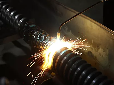
Remove polymer and loose deposits without grinding away the edge that you intend to measure. Mark any area where cleaning exposed pitting, coating loss or metal transfer.
Record the temperature
Write down part, instrument and room temperature. NIST explains that dimensional results away from the 20 °C reference temperature carry thermal-expansion uncertainty.
Identify the orientation
Choose a repeatable zero-degree reference on the barrel and screw. Without an orientation reference, a second inspection cannot confirm whether an oval pattern moved or grew.
Photograph before polishing
Take overall and close-up photographs with zone labels and a scale reference. Surface evidence can disappear during cleaning or repair preparation.
For precision dimensional work, 20 °C is the international standard reference temperature. NIST's paper on the 2016 revision of ISO 1 explains that the reference applies to geometrical and dimensional properties. A maintenance shop does not become a calibration laboratory by waiting for exactly 20 °C. The practical point is to stabilize the parts, record temperature and include temperature effects in the measurement uncertainty when they matter.
What we refuse to do from a dirty sample
We will not increase the new screw diameter because one polymer-covered flight looks small. First we need a clean surface, repeated readings and the mating barrel data. Machining an oversized replacement from a contaminated sample can turn a measurement shortcut into metal contact after heat-up.
Build one station map for both parts
Use the same axial origin for the screw and barrel wherever possible. The station spacing does not need to be perfectly uniform. Put more stations around severe damage, geometry transitions, mixing elements, a vent, a barrier-flight transition or any area where the process symptom points to a local problem.
| Station field | What to record | Why our factory needs it |
|---|---|---|
| Axial location | Distance from the agreed datum, plus zone name | Lets screw and barrel readings be paired at the same working position |
| Angular direction | 0°, 90°, 180° and 270°, or another documented pattern | Shows ovality and one-sided wear instead of hiding it in an average |
| Measured value | Screw OD or barrel ID, with unit and decimal resolution | Supports clearance and change-over-time calculations |
| Surface observation | Polishing, scoring, pitting, coating loss, flight rounding or metal transfer | Connects the number with a likely wear mechanism |
| Measurement record | Instrument ID, master/reference, operator, date and temperature | Makes the reading repeatable and suitable for drawing review |
How we measure the screw outside diameter
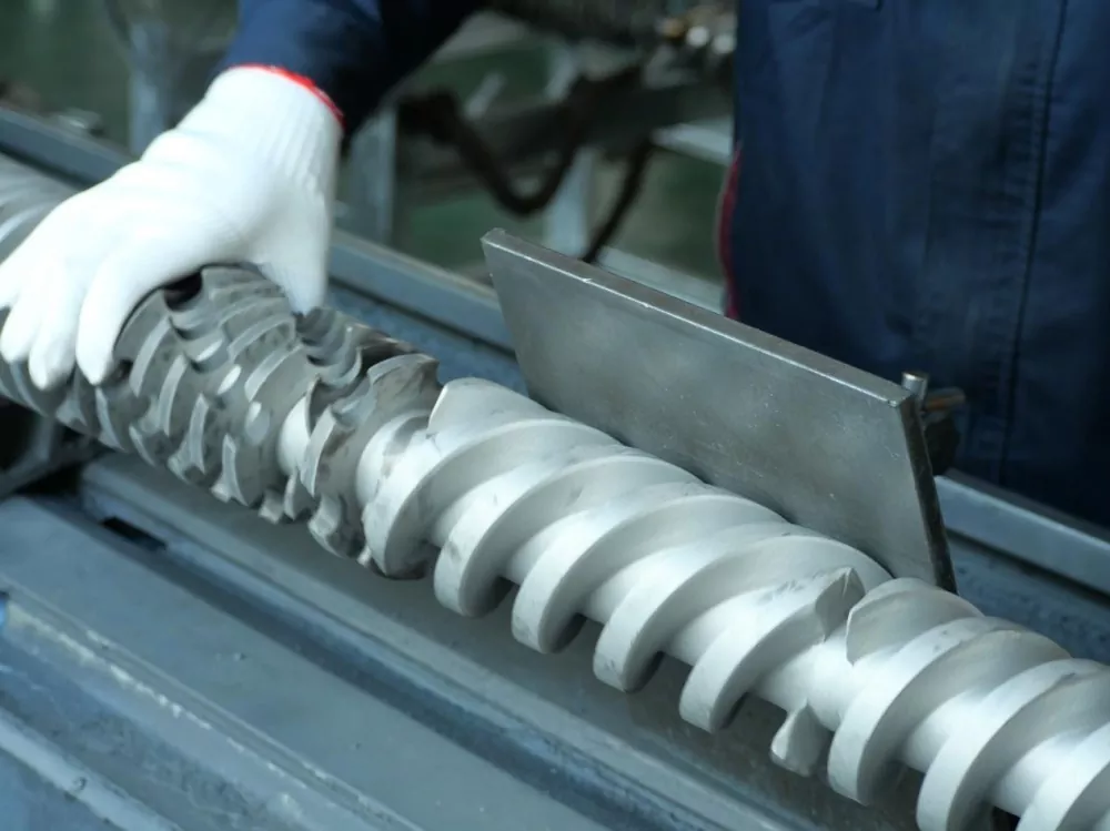
Use a micrometer or another diameter measurement system with suitable range, contact geometry, resolution and calibration status. A caliper is useful for identifying features and making coarse checks. We would not approve a close running clearance from a caliper alone, especially when flight edges are rounded or alloy is worn unevenly.
- Mark each axial station. Put the station beside the flight section being measured, not on an undefined nearby point.
- Measure across the flight tips. Keep the instrument square to the screw axis and avoid seating the contact on a burr, coating chip or polymer deposit.
- Rotate and repeat. A reading in one angular direction can miss eccentric or one-sided wear. Record the maximum and minimum values rather than only an average.
- Repeat suspicious readings. If one value breaks the pattern, clean the contact area, reset the instrument and measure again. Keep the first value in the raw record if traceability matters.
- Map the surface beside the number. Note whether the measured loss appears at a flight tip, side, root, mixing feature or hardfaced region.
How we measure the barrel bore
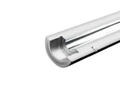
The barrel often decides whether a screw-only replacement will work, yet it is the part most likely to receive one reading at the discharge end. That is not enough. A bore can be acceptable at the opening and enlarged deeper in the metering or compression zone.
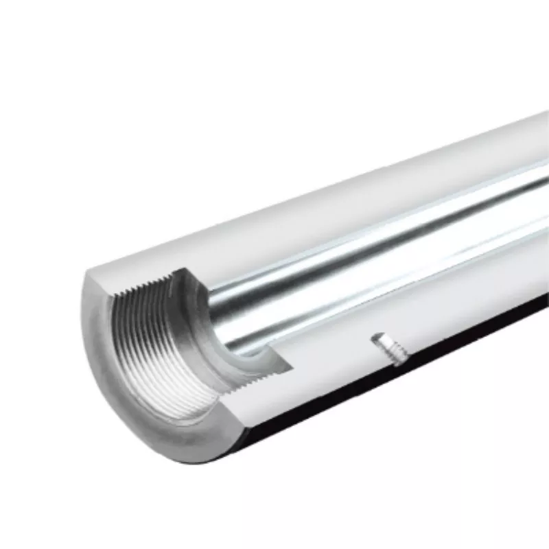
Use a bore gauge, internal micrometer or another inside-diameter system suited to the bore size and measurement depth. Set or verify it against a suitable master or reference. Mitutoyo's official bore-gauge instructions describe master setting with a master ring and measuring the minimum inside-diameter value. Follow the instructions for the actual instrument in use rather than treating one tool family as universal.
- Define depth from a physical datum. Use a flange face or another documented reference. A note such as "middle of barrel" cannot be repeated accurately.
- Reach the matching station. Confirm that extension rods and the gauge range suit the depth without excessive deflection or uncontrolled contact.
- Rock or sweep according to the instrument method. Find the indicated diameter correctly, then repeat the reading. Do not copy a random value while the head is tilted.
- Measure more than one angular direction. Record maximum and minimum ID at the station. This is where an oval or one-sided wear pattern appears.
- Inspect the surface. Scoring, pitting and smeared metal can matter even when a few diameter readings look reasonable.
Calculate clearance correctly and name the definition
The word "clearance" causes avoidable mistakes because some drawings mean the full difference between diameters, while others mean the gap on one side. We want the definition written beside every value.
Use both formulas
Diametral clearance = measured barrel ID minus measured screw OD
Radial clearance = (measured barrel ID minus measured screw OD) divided by 2
For an illustrative calculation only, if the barrel ID at one station is 90.00 mm and the corresponding screw OD is 89.72 mm, diametral clearance is 0.28 mm and radial clearance is 0.14 mm. This example explains the definitions. It is not an acceptance value for a 90 mm Nanhaiya screw.
Nanhaiya's article on wear resistance and high-precision processing publishes a 0.10 to 0.20 mm screw-to-barrel clearance reference depending on diameter. The page does not replace a project drawing, and a replacement order must still state whether its clearance callout is radial or diametral.
Clearance has a process effect. An open-access paper in Polymers, Leakage-Flow Models for Screw Extruders, models the leakage flow through the flight clearance as part of the melt-conveying problem. The paper also shows why clearance cannot be evaluated without geometry, material behavior and pressure conditions.
Three numbers that should never be averaged into one
Keep minimum clearance, maximum clearance and out-of-round visible by station. One average can hide the tight side that risks contact and the open side that permits more leakage. For our factory review, the pattern is often more useful than a single headline value.
What the wear pattern tells us
Measurements show where material has moved. Surface condition and machine history help explain why. We use the two together before recommending a copy, a localized surface upgrade or a matched replacement.
| Measured pattern | What we check next | Factory decision it may change |
|---|---|---|
| Screw OD decreases while barrel ID remains stable | Flight-tip wear, coating or hardfacing condition, resin and filler history | Screw-only repair or replacement may be reasonable |
| Barrel ID grows through one axial zone | Pressure and wear load in that zone, barrel liner condition, corresponding screw wear | A new screw alone may not restore the intended working gap |
| Large difference between angular readings | Alignment, screw straightness, gearbox output, support and signs of metal contact | Correct the mechanical cause before installing new parts |
| Pitting without large uniform diameter loss | Resin chemistry, additives, moisture, cleaning agents and temperature history | Surface material selection may matter more than simply adding diameter |
| Rounded flights and smooth polishing in a filled-material zone | Filler type, percentage, recycled contamination and location of alloy protection | Place the working layer where abrasion occurs instead of upgrading every surface |
| Deep score on both screw and barrel | Foreign material, bent screw, bearing or alignment problem | Do not order a direct copy until the contact cause is removed |
Nanhaiya's black-line troubleshooting article states that an increased screw-to-barrel gap can trap material and that wear-generated metal powder can enter the product. That article also recommends checking raw material, cleaning and accessories before blaming the screw or barrel. We use the same logic here. A wear map is useful evidence, but it does not turn every quality problem into a replacement order.
Have measurements but no clear decision? Send the station sheet, photos and machine duty to info@nhyscrew.com or WhatsApp +86 135 8708 2002. We will review the wear pattern before discussing a replacement single screw.
Send an inspection inquiryHow to use Nanhaiya's published reference values
Our website contains useful process and product figures. They come from different pages and product contexts, so we do not copy them into a replacement drawing as one universal specification. We use them to start the technical conversation, then confirm the value that belongs to the actual part.
| Nanhaiya website reference | Published value | How we use it in a wear review |
|---|---|---|
| Wear-resistant precision screw article | Clearance reference of 0.10 to 0.20 mm, depending on diameter | Prompts us to confirm screw diameter, barrel bore and the radial or diametral definition |
| Single screw barrel guide | ±0.001 mm tolerance, 0.015 mm/m straightness and Ra0.4 surface roughness references | Shows why instrument capability, temperature and a controlled drawing matter when small dimensional differences affect the decision |
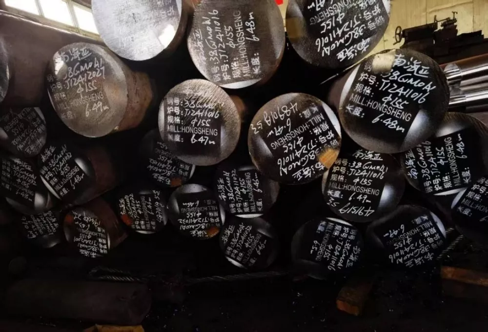
| Black-line troubleshooting article | 38CrMoAlA, nitriding depth of 0.50 to 0.70 mm, HV950 to 1050 and Ra0.4 for the described screw configuration | Provides surface-system context. It does not state how much usable layer remains on a particular worn screw |
| Extruder single screw barrel product page | Nickel and tungsten alloy working layer of 2 to 3 mm and HRC58 to 65 for the published configuration | Helps identify whether a worn barrel has a liner or working layer that needs material-specific repair assessment |
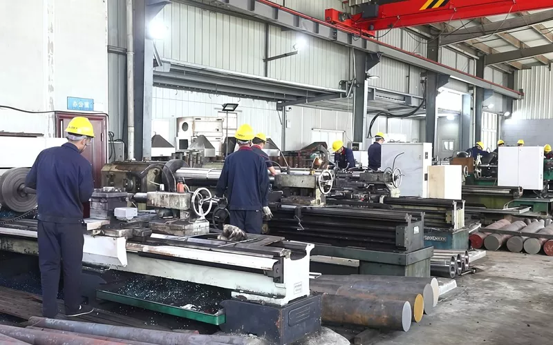
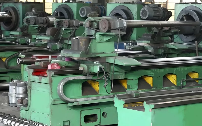
| Production equipment page | CNC saw feed error no more than 0.1 mm, workpieces up to 6 m on listed lathes, and 0.02 mm drilling and milling positioning accuracy | Describes Nanhaiya's published equipment capacity. Final part acceptance still comes from the inspection plan and approved drawing |
What a useful wear report should contain
A spreadsheet full of diameters can still fail if nobody knows where the measurements were taken. Our preferred record connects geometry, location, surface condition and production history.
Part identity
Machine make and model, part number, drawing revision, screw direction, material and treatment if known.
Station drawing
Axial datum, station distances, zone names, angular zero and photographs showing the marks.
Raw measurements
Every screw OD and barrel ID reading, not only averages, plus repeated values where a result was questioned.
Calculated condition
Maximum and minimum diameters, out-of-round, diametral clearance and radial clearance by station.
Measurement trace
Instrument, master or reference, calibration status, operator, date and temperature.
Production context
Resin, filler, recycled content, output, speed, symptoms, operating hours if documented and recent process changes.
The wear report answers the condition question. Our screw-only versus matched-pair decision guide explains how that condition changes replacement scope. The replacement single screw specification guide then turns the decision into a controlled drawing and RFQ package.
Questions maintenance teams and buyers ask us
How do you measure wear on an extruder screw?
How do you measure wear inside an extruder barrel?
How is screw-to-barrel clearance calculated?
Can I measure screw and barrel wear with a caliper?
How many locations should be measured?
When do wear measurements support replacing both the screw and barrel?
Send us the map, not one diameter
We can do much more with six imperfect but clearly located readings than with one precise number from an unknown point. Send the screw OD map, barrel ID map, orientation, surface photos, material and production symptoms. We will tell you what information is still missing before a replacement drawing is approved.
Nanhaiya manufactures custom single screws and barrels, including nitrided and alloy-protected configurations for different extrusion materials and wear conditions. We select the working surface after we understand where and why the current pair has worn.