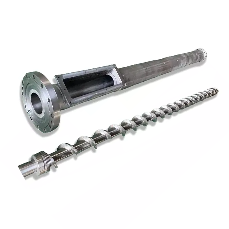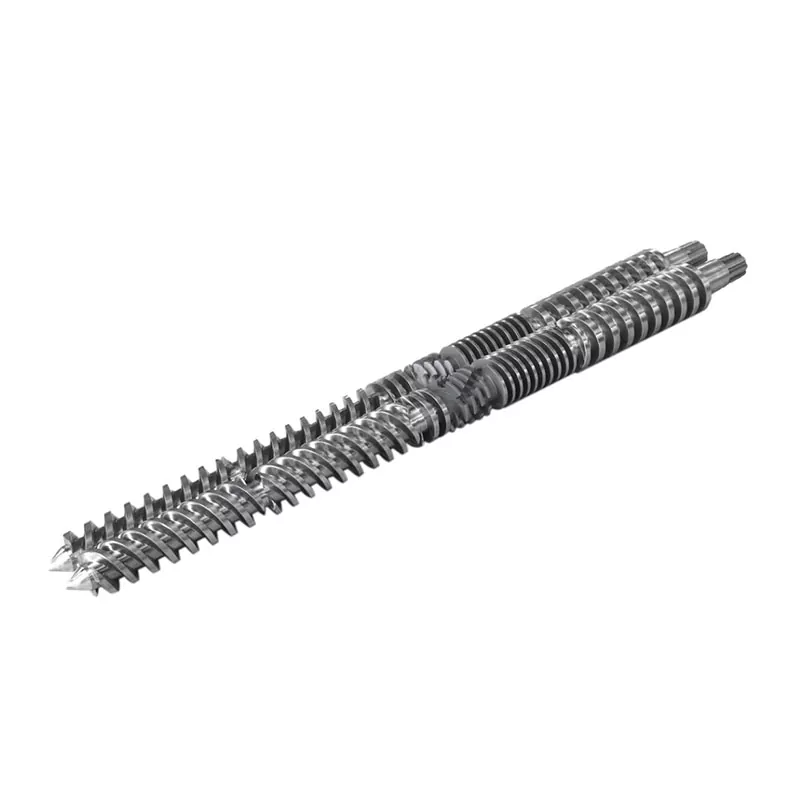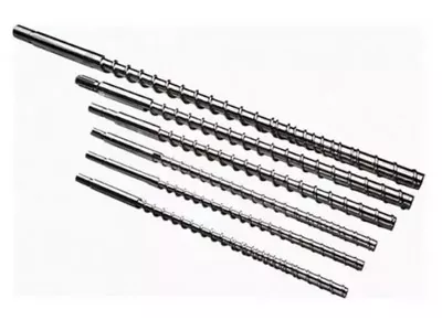

A slow recovery timer can point to a feeding problem, a changed process or worn hardware. The useful diagnosis tells you which one, and whether it is actually costing you cycle time.
If injection molding screw recovery takes too long, first confirm that it delays the cycle. Then check feed continuity, actual screw speed, back pressure and temperature against a stable reference run. Inspect geometry and wear when those checks do not explain the loss. Replace components only after identifying the limiting function.

First, establish whether recovery is on the cycle's critical path
Screw recovery is the plasticizing and metering stage: the screw rotates, prepares the next shot and retracts as melt accumulates in front of it. It is different from injection, when the screw moves forward to deliver that shot. Check your controller's timer definition, especially whether it includes a delay or decompression.
Recovery often overlaps part of the cooling sequence. Its effect on total cycle time therefore depends on when recovery starts and which machine action must wait for it to finish. Read the sequence trace rather than assuming that every second removed from recovery removes a second from the cycle.
| Recovery duration | Wait beyond the window | What the change means |
|---|---|---|
| 12 seconds | 2 seconds | Recovery is delaying the next action. |
| 9 seconds | 0 seconds | The 3-second recovery improvement removes 2 seconds of waiting. |
| 7 seconds | 0 seconds | Another 2 seconds off recovery brings no further cycle reduction in this example. |
Our first question is whether the machine is waiting for melt or simply reporting a number you would like to reduce. If recovery already fits comfortably inside the available window, we would focus on consistency and melt quality before recommending a higher-output screw.
For a broader explanation of the assembly, see our injection molding screw barrel guide. Here, the objective is narrower: establish why recovery changed and what action the evidence supports.
A sudden change and a gradual decline need different starting points
Save a reference before adjusting the machine. Compare the same resin grade, regrind ratio, shot setting, mold and temperature condition. Record individual cycles as well as the average; an occasional very slow recovery can disrupt production even when the average appears acceptable.
| Observed pattern | Check first | Evidence worth recording |
|---|---|---|
| Sudden increase after a material or recipe change | Feed form, regrind, drying condition and transferred settings | Material lot, blend ratio, particle condition and before/after process records |
| Intermittent slow cycles with normal cycles between them | Feed interruption, bridging and actual-speed variation | Recovery trace, loader activity and actual RPM for the same cycles |
| Recovery worsens gradually under a stable duty | Verify operating conditions, then inspect wear | Historical recovery data and measured screw/barrel dimensions |
| High load and actual RPM below the command | Machine drive, torque limit and thermal condition | Actual versus commanded RPM, load trend and machine alarms |
| Problem begins immediately after a component replacement | Installed part identity, dimensions, geometry and assembly | Approved drawing revision, fitted components and commissioning settings |
These patterns decide the investigation order; none is proof by itself. An abrupt fault with noise, scoring or abnormal load needs prompt machine-service attention, even if the timing initially resembles a process problem.
Confirm that pellets reach the screw continuously
A full hopper does not establish that the screw is being fed. Check the loader, shutoff slide, material path and feed-throat cooling. Look for an interruption that coincides with the slow cycles before changing the compression section or ordering a new screw.
Asahi Kasei's Asaclean guidance on feed-throat bridging explains how heat near the rear barrel zone can soften pellets prematurely. The pellets can clump and obstruct the passage, leaving the screw short of material even though resin remains above it.
Check what changed in the feed itself. A different regrind ratio, more fines or irregular particles deserves attention. Celanese specifically links regrind particle quality to feeding and recovery issues in its Vectra® LCP processing guide. Its recommendations are material-specific, but they provide a concrete reason to record particle condition rather than only the resin name.
If recovery deteriorates after a regrind change, we would compare it with an approved reference feed before changing hardware. If the old recovery behavior returns, the feed investigation has earned priority. That result gives the factory much better direction than a request for a “faster screw.”
Drying still needs to meet the resin supplier's requirements. Do not assume that moisture is the explanation for every timing problem, or that acceptable recovery proves the resin is dry enough. Processability and final part quality need separate checks.
Check actual speed, back pressure and melt temperature together
Read actual RPM, not just the setpoint
If the command is unchanged but the screw is turning more slowly, inspect the machine's operating limits and drive behavior. A geometry recommendation cannot resolve an unexplained gap between requested and delivered speed. Record actual speed through the recovery stroke, especially where the slow-down begins.
RPM also needs the screw diameter to mean much. Our injection molding screw range includes diameters from 30 to 170 mm. Transferring a rotational-speed setting between different diameters changes the peripheral speed at the screw surface.
Peripheral speed, m/s = π × diameter, mm × RPM ÷ 60,000
At 100 RPM, a 40 mm screw has a peripheral speed of about 0.209 m/s; a 60 mm screw reaches about 0.314 m/s. These are calculated examples, not recommended settings or direct calculations of melt shear rate.
Use the actual resin grade's processing guidance and the machine limits to judge speed. Increasing RPM is useful only if the machine can deliver it and the resulting melt remains acceptable.
Find out why the back pressure is set where it is
Back pressure resists the screw's retreat during recovery and affects how the material is plasticized. If it was increased to correct a mixing or metering concern, reducing it simply to improve the timer may bring that quality problem back. Confirm whether the displayed pressure is hydraulic or specific plastic pressure before comparing machines.
A universal back-pressure recommendation is particularly unhelpful. For Vectra LCP, Celanese specifies minimal back pressure, 5-15 bar specific, and warns about overheating and fiber damage with excessive pressure. That is guidance for Vectra, not a setting to copy into a PP, ABS or PC process.
Check the melt before accepting the faster setting
Barrel setpoints do not fully describe the thermal condition of the melt. Follow an approved melt-temperature measurement procedure, verify the heater and sensor system, and compare part quality after a controlled change. A shorter recovery time with discoloration, unmelted material or poorer consistency is not a successful adjustment.
Change one relevant variable at a time and allow the process to stabilize. The Vectra troubleshooting guidance uses this same staged approach. Keep the trial inside the approved operating window for the material you actually run.
Separate a worn conveying section from a leaking check ring
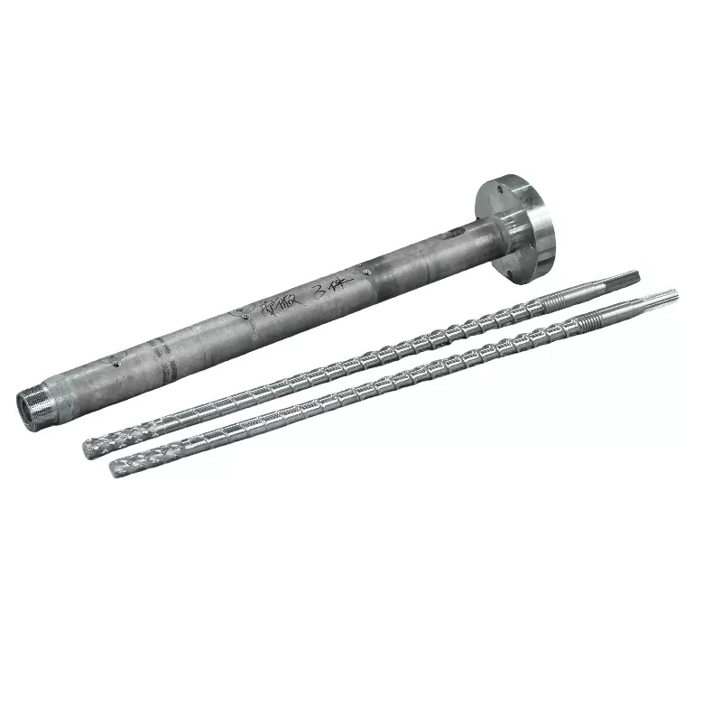
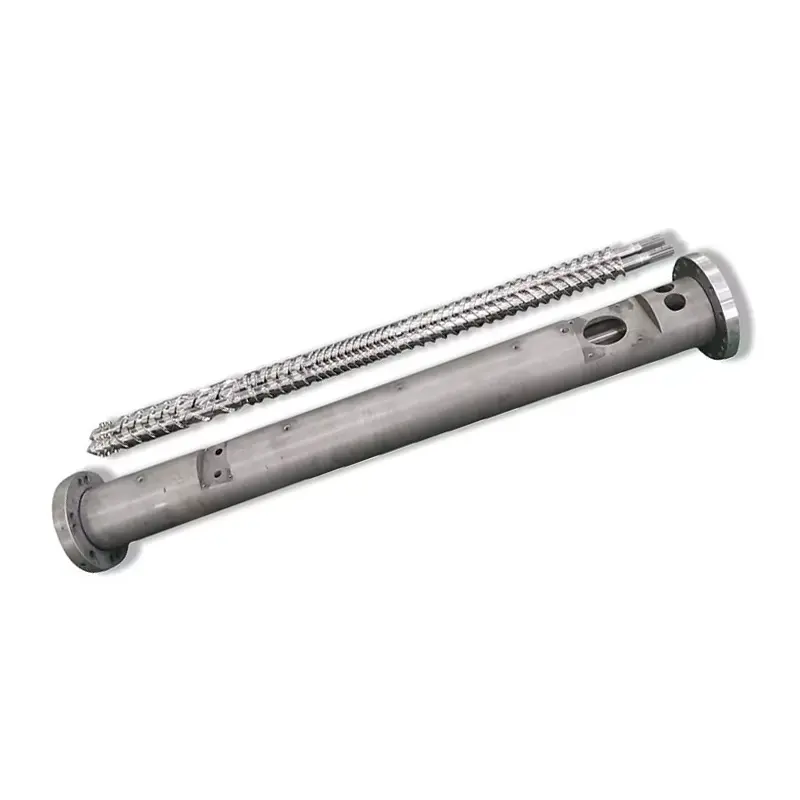
When feeding and operating conditions are comparable but recovery keeps deteriorating, the condition of the screw and barrel deserves inspection. Measure the flight outside diameter and barrel bore at defined positions against the drawing or established inspection limits. Inspect surface damage as well as dimensions.
The screw-front assembly needs a different test. During recovery, the non-return valve allows melt to move forward; during injection, it should seal against backward flow. A leaking valve can affect shot consistency, but that does not establish that the screw's plasticizing section has worn out.
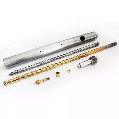
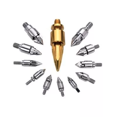
If cushion or shot weight also varies, include the machine manufacturer's non-return-valve test in the investigation. Our screw tip selection guide covers the ring, seat and mating dimensions in more detail.
We would not authorize a complete screw-and-barrel replacement on a slow timer alone. Conversely, a new screw should not go into a worn barrel without checking the resulting fit. Ask for a dimensional report that identifies the measurement positions and the wear limits used to reach the recommendation.
When does a different screw design make sense?
A design review becomes useful when the current geometry cannot meet the intended duty within acceptable operating conditions. This may follow a resin change, a larger shot requirement or a shorter available recovery window. Keep it separate from restoring a previously successful process that has simply deteriorated.
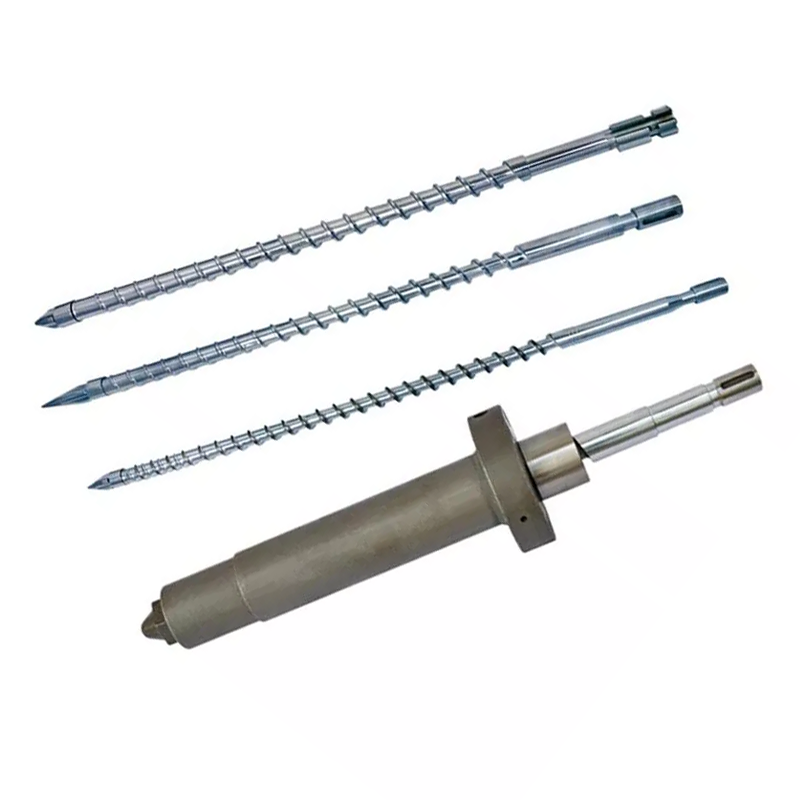
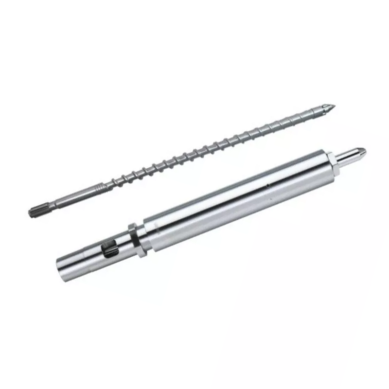
Our two injection screw product families illustrate a relevant design choice:
| Nanhaiya design | Compression section | How we would use it in the review |
|---|---|---|
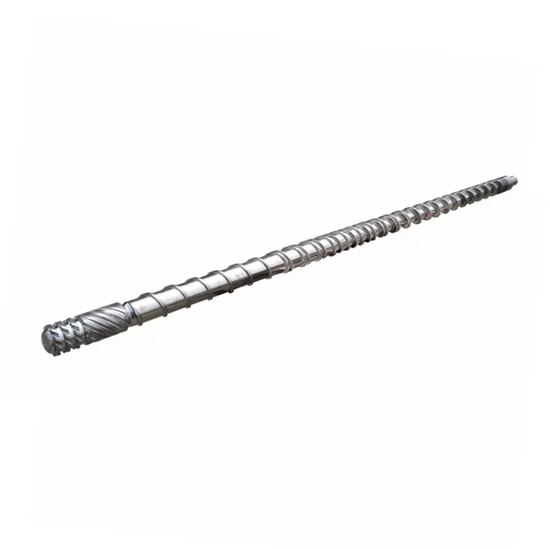
| Gradual injection molding screw | Typically 40%-60% of total screw length, approximately 50% in the product description | A longer, gradual reduction in channel depth for duties that need controlled plasticization. Evaluate the exact resin, shot and thermal behavior. |
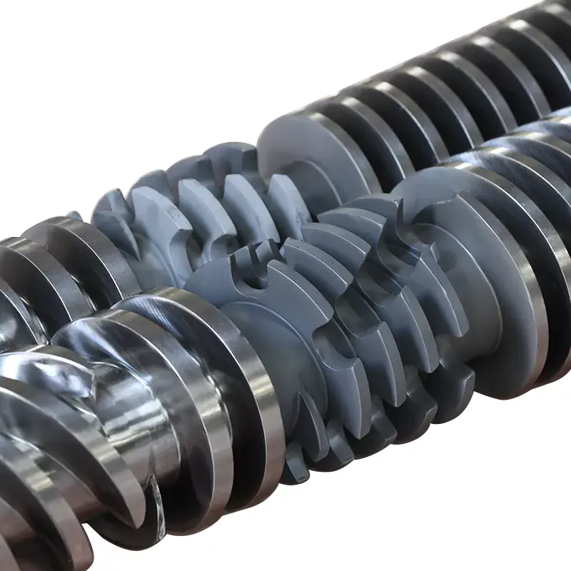
| Mutant injection molding screw (abrupt-compression design) | Approximately 5%-15% of total screw length | A shorter transition with a sharper reduction in channel depth. Evaluate melting duty and thermal uniformity before selecting it to address a capacity limitation. |
Our gradual design covers applications including PS, PC and ABS; the abrupt-compression family includes applications such as PE and PP. These product routes help start the discussion. They do not replace the resin-grade and machine review, especially with fillers, regrind or a demanding quality specification.
Surface treatment addresses wear, not a blocked feed throat
Both product families use 38CrMoAlA steel. Their product-detail specifications include the following treatment options, which belong in the replacement discussion when inspection identifies wear:
| Property | Product-detail value | What it means for the inquiry |
|---|---|---|
| Nitriding hardness | HV900-1100 | Specify the treated surfaces and inspection requirement. |
| Nitriding depth | 0.5-0.8 mm | Identify the selected treatment; do not infer service life from depth alone. |
| Nickel-tungsten alloy hardness | HRC55-62 | Review the alloy with the actual resin, filler and wear pattern. |
| Alloy layer depth | 0.8-2.0 mm | Define the reinforced areas on the agreed component specification. |
Our gradual screw product details describe reinforcement of vulnerable areas with nickel-tungsten alloy. From a factory perspective, we want the proposed protection to correspond to the measured wear. A more expensive surface does not repair inadequate feeding or establish that the screw geometry suits the resin.


Turn the diagnosis into a specific action
Keep the recommendation as narrow as the evidence allows. A feed interruption calls for a feed-system correction. A speed command the machine cannot maintain calls for a machine review. Confirmed valve leakage calls for a valve and interface assessment. Measured screw or barrel wear supports a component replacement or a qualified refurbishment evaluation.
If the assembly is in acceptable condition but the new production duty exceeds its practical plasticizing capacity, send the design brief. Nanhaiya provides custom screw design, machining and alloy spray welding. Our production equipment includes CNC lathes for workpieces up to 6 meters long and five-axis machining for complex flights and flange structures.

Send the record that explains the problem
- Machine maker and model, screw diameter, assembly drawing and fitted screw-tip details.
- Resin grade, filler loading, regrind ratio and particle condition.
- Recovery time by cycle, actual and commanded RPM, back pressure with its pressure basis, and load or alarm records.
- Shot setting, cushion, part and runner weight, temperature records and the available recovery window.
- Changes already tested, their effect on part quality, and any dimensional wear report.
For commissioning, agree on the resin, shot, operating window and acceptable part quality. Then compare recovery repeatability and actual total cycle time. A faster isolated plasticizing test is insufficient if the production mold still waits or the parts fail inspection.

Need a screw or barrel proposal for a confirmed recovery limitation?
Send Nanhaiya the drawing and operating record, including what changed and what your line needs to achieve. Tell us whether you are restoring the original duty or preparing for a different material or cycle requirement.
Send your drawing and process dataView injection molding screwsDiscuss on WhatsApp
Zhoushan Nanhaiya Plastic Machinery Co., Ltd.
Email: info@nhyscrew.com
Phone: +86-13505809643 | Mobile: +86-13587082002
Block C, No. 2 West Section, Xingzhou Avenue, Dinghai District, Zhoushan City, Zhejiang Province, China.
Contact Nanhaiya
Frequently asked questions
What is a normal injection molding screw recovery time?
There is no universal number. Recovery time depends on the resin, shot requirement, screw geometry, machine capability and operating settings. Compare it with the time available in the actual machine sequence and with a stable reference run using the same material and shot.
Does faster screw recovery always shorten cycle time?
No. It shortens the cycle only when unfinished recovery is delaying the next permitted machine action. If recovery already finishes within the available overlap window, making it faster may leave total cycle time unchanged.
Why does the screw rotate but retract very slowly?
Check whether resin is reaching the screw, whether back pressure changed, and whether actual screw speed matches the command. Feed bridging, inconsistent regrind, process conditions and worn components are possible branches to investigate. Rotation alone does not prove that the screw is conveying enough material.
Should I increase RPM to fix slow recovery?
Only after checking feeding, actual speed, back pressure and the resin's processing limits. Judge any change by melt quality, actual melt temperature and repeatability as well as recovery time. Do not use more speed to conceal an unresolved feeding or wear problem.
Does a leaking check ring prove the whole screw is worn?
No. Check-ring sealing and screw-barrel conveying are different functions. Investigate cushion or shot-weight variation with the machine manufacturer's valve test, and use dimensional inspection to establish screw and barrel wear.
What does Nanhaiya need to assess a replacement?
Send the machine model, screw diameter and drawing, resin grade and filler, regrind details, actual recovery records, screw speed and back-pressure settings, temperature records, and any wear measurements. Include the required cycle and part-quality criteria so the replacement has a defined job.
Continue with the injection molding screw barrel selection guide, or examine the screw tip and check-ring replacement checklist if the evidence points to the front-end assembly.