
A barrel flange looks simple until the new part reaches the machine. Then a small error in the register, bolt circle, sealing face or melt passage can stop installation. This guide shows purchasing and maintenance teams how to turn an old sample, machine interface and operating duty into a controlled flange specification.
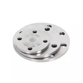
Quick answer
To buy an extruder barrel flange, send a controlled drawing that identifies the bore, outside diameter, thickness, locating register, bolt pattern, sealing face, material, surface treatment and mating parts. Add the actual temperature and pressure basis, extruder or die-head model, quantity and inspection requirements.
Do not order a custom machine flange from the words "ANSI," "DIN," "JIS" or "PN16" alone. Those references can define a standard pipe flange only when the complete standard designation and service basis are stated. An extruder connection usually needs its own interface drawing, even when one side follows a recognized flange pattern.
First identify what kind of flange you are buying
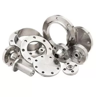
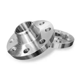
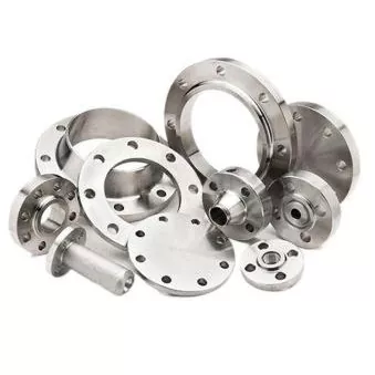
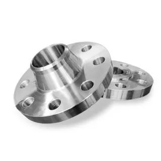
Procurement errors often begin when three different components are all called a flange. A standard pipe flange, a custom extruder barrel flange and a transition adapter can look similar in a photograph. They are not specified in the same way.
| Component | What defines it | Main procurement risk |
|---|---|---|
| Standard pipe flange | Exact standard, edition, nominal size, class or PN, facing, material, bore and connection type | A short label such as "DIN flange" can refer to more than one dimensional and rating system |
| Custom extruder barrel flange | Controlled machine drawing, mating barrel or adapter, register, bolt pattern, melt bore, sealing feature and service duty | Using a pipe-flange table for a machinery interface that has custom locating and flow features |
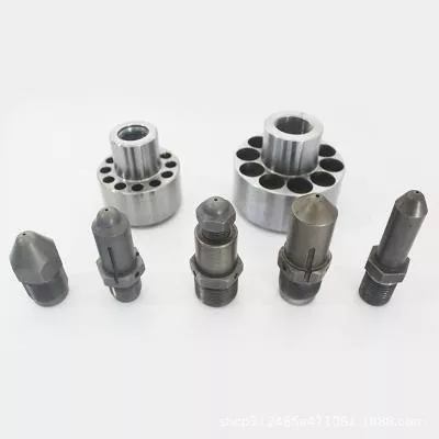
| Die-head adapter flange | Two interfaces plus the internal melt transition, orientation, support and sensor or screen-pack requirements | Both ends fit separately, but the assembled flow path, centerline or bolt orientation does not |
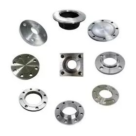
Nanhaiya's current barrel flange range covers round steel flanges with flanged connections and customizable port sizes. ANSI, DIN and JIS patterns are available, along with fully customized dimensions for plastics, chemical, granulation and machinery applications.
Our factory view: the standard name starts a technical conversation; it does not finish the drawing. We first ask where the part sits, what locates it, what seals it and what passes through it. Once those functions are clear, the correct dimensions become much easier to control.
The dimensions that decide whether the flange fits
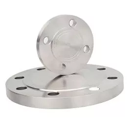
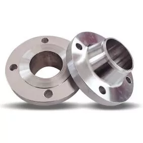
A useful drawing separates size from function. The bolt holes create clamp force, the register locates the parts, the face carries the seal and the bore carries the melt or process medium. Asking one feature to compensate for another creates difficult assembly and uncertain sealing.
| Drawing feature | Why it matters | What the buyer should state |
|---|---|---|
| Outside diameter | Controls envelope, tool access and clearance near heaters, guards or supports | Nominal size, tolerance and any restricted sector |
| Central bore or melt passage | Controls flow continuity and the internal step at the joint | Diameter, tolerance, transition shape, direction and surface requirement |
| Overall and local thickness | Affects bolt engagement, stiffness, alignment and assembled length | Datum faces, thicknesses, counterbores and hub length |
| Locating register or spigot | Establishes concentric assembly instead of relying on bolt-hole clearance | Male or female feature, diameter, depth, fit and lead-in |
| Bolt pattern | Provides the clamping connection and fixes angular orientation | Quantity, pitch-circle diameter, hole size, thread, depth and angular datum |
| Sealing face | Creates the intended contact with a gasket, ring, groove or metal face | Facing type, dimensions, finish, seal specification and allowable damage |
| Geometric controls | Keep the bore, register and sealing face correctly related | Datums plus required flatness, perpendicularity, position, coaxiality or runout |
| Orientation features | Align heaters, sensor ports, keyways, guards or asymmetric mating parts | Clocking angle from one unambiguous datum |
ISO 286-1 provides an international system for linear-size tolerances and fits, including cylinder features and the basic-hole and basic-shaft concepts. ISO 1101 provides the symbol language for form, orientation, location and runout controls. These standards help express the requirement, but the designer must still choose the functional datums and allowable values.
Bolt-hole clearance is not a locating system. If the connected die head or adapter must be concentric with the barrel bore, define a register or another controlled locating feature. Tightening bolts while forcing two misaligned bores together can damage the face, seal or fasteners and leave a harmful internal step.
ANSI, DIN, JIS and PN are not complete purchase descriptions
Nanhaiya offers ANSI, DIN and JIS options or a customized standard. That range is useful when a flange joins established plant piping or must match an existing regional pattern. The quotation still needs the exact document, edition, nominal size, rating, face, material and any project modification.
ASME B16.5, for example, is titled for pipe flanges and flanged fittings from NPS 1/2 through NPS 24. Its scope addresses pressure-temperature ratings, materials, dimensions, tolerances, marking and testing. This is a strong framework for components within its scope, but its title does not turn every extruder connection into a B16.5 flange.
Practical distinction: if the flange is part of a pressure-piping boundary, use the applicable piping rules and qualified engineering review. If it is a custom machine interface, control it with the approved equipment drawing and operating duty. If it performs both roles, the purchase package must satisfy both sets of requirements.
Standard pattern
State the standard number, year or edition, size, class or PN, facing, material group and mating component. List any deviation explicitly.
Custom pattern
Make the signed drawing the authority. A reference to a standard can still define selected threads, fits, symbols or test methods.
Mixed interface
Show which face follows a standard and which face is customized. Define the internal transition and angular relationship between both ends.
Our factory view: "same as the old flange" is useful context, but it is not an inspectable requirement. We put the exact interface on a drawing and ask the buyer to approve it. This gives production, inspection and installation teams the same answer when a measurement is questioned.
Pressure class cannot be separated from temperature and material
Nanhaiya's barrel flange page lists PN6, PN10, PN16, PN25, PN40 and PN63 options. Treat these as available specification categories, not as one universal working-pressure statement. A usable rating depends on the governing standard, material, temperature, geometry, bolting, seal and system design.
Polymer processing adds conditions that a short flange label cannot describe. The connection may see hot melt, heating and cooling cycles, machine vibration, die-head weight, assembly loads and cleaning. State normal and maximum conditions, but keep design conditions separate from routine process settings.
| Duty input | Why the manufacturer needs it | Evidence to attach |
|---|---|---|
| Normal and maximum temperature | Affects material behavior, seal selection, thermal movement and rating basis | Process sheet, heater settings and measured operating range |
| Normal and maximum pressure | Defines the mechanical and sealing duty under the applicable design method | Instrumentation range, operating records and design requirement |
| Pressure medium | Molten polymer, gas, liquid or plant piping can require different design and cleaning controls | Material name, formula, safety data and process diagram |
| External load | A heavy die head or unsupported piping can add bending load at the flange | Assembly weight, center of gravity, supports and installation drawing |
| Thermal cycles | Repeated expansion and contraction can affect preload, alignment and sealing | Start and stop frequency plus heating and cooling sequence |
| Applicable code or customer rule | Determines calculations, material records, marking, testing and approval responsibility | Exact document, edition and project specification |
Do not select a higher PN number as a stand-alone cure for leakage. Leakage can come from face damage, a wrong seal, distortion, contamination, poor alignment, unsuitable bolting or thermal movement. Find the failure mechanism before changing the class or tightening method.
Choose material and surface treatment for the real environment
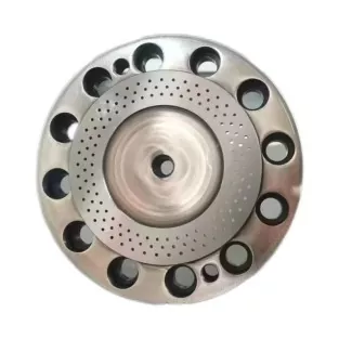
Nanhaiya manufactures barrel flanges from carbon steel, stainless steel and alloy steel. Available surface treatments include sandblasting, galvanization and nickel plating, with other treatments available to customer requirements. The approved drawing should state an exact grade and treatment scope, not only a broad material family.
| Option | Why a buyer may consider it | Questions to resolve before approval |
|---|---|---|
| Carbon steel | General machinery strength and economical manufacture where the environment is controlled | Exact grade, corrosion protection, weldability, temperature basis and exposed surfaces |
| Stainless steel | Corrosion resistance or a cleaner exposed surface for a defined process environment | Exact grade, chemical exposure, galling risk, mating materials and fabrication route |
| Alloy steel | Mechanical or thermal duty that calls for a specified alloy and treatment route | Grade, heat treatment, hardness, toughness, machinability and inspection records |
| Sandblasted surface | Surface preparation or a specified external finish | Which faces are treated and which precision or sealing faces must be protected |
| Galvanized or nickel-plated surface | Additional surface protection for an agreed environment | Coating material, thickness criterion, masked areas, dimensional allowance and repair method |
A coating does not correct an unsuitable base material, weak geometry or damaged sealing face. It can also change a close-fitting register if the drawing does not define masked surfaces and final dimensions. Decide whether the tolerance applies before treatment or to the finished part ready for assembly.
Our factory view: we separate working faces from protected external faces. A seal land, locating diameter or tight bore should not receive a coating by accident. Marking treatment boundaries on the drawing is much safer than resolving them after the finished parts arrive.
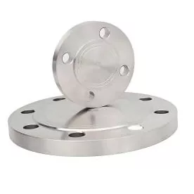
How to measure a replacement barrel flange
An old part provides valuable physical evidence, but it may no longer represent the intended geometry. A register can wear, a face can be skimmed during repair and heat can distort the plate. The original machine or assembly drawing remains the best starting authority when it is available.
- Photograph the installed assembly. Record flow direction, component order, centerline, supports, heaters, sensors and access before disassembly.
- Identify both mating components. Note the barrel, adapter, screen changer, confluence core, gearbox-side structure or die head connected to each face.
- Clean without changing the evidence. Remove polymer and loose contamination without rounding edges or polishing away wear marks that explain the failure.
- Establish datums. Choose the primary sealing or mounting face, the bore or register axis and one angular feature before recording dimensions.
- Measure each interface. Record bore, outside diameter, thickness, every step and depth, bolt pattern, threads, counterbores, face features and orientation.
- Measure the mating parts. A copied worn flange can reproduce the old error. Verify the actual male and female registers, available bolt engagement and seal location.
- Resolve conflicts on the new drawing. Compare the sample, original drawing and mating measurements, then approve the dimension that restores the intended function.
Minimum photo set: one installed overview, both flange faces, a side view, the barrel or die-head nameplate, every mark or part number, the seal, and close views of damage. Place a scale beside the part for orientation, but never calculate critical dimensions from perspective photos.
For twin-screw or multi-component projects, check angular orientation carefully. A bolt pattern may be symmetric while the melt opening, heater terminal, sensor port or support is not. The assembly can bolt together and still be rotated into an unusable position.
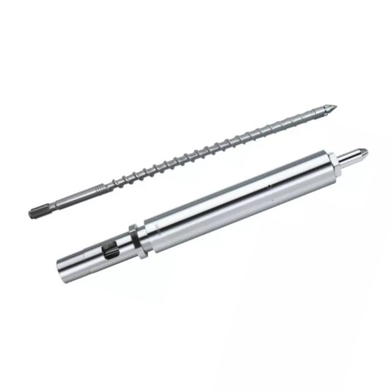
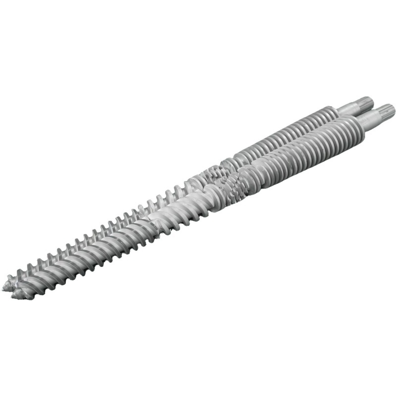
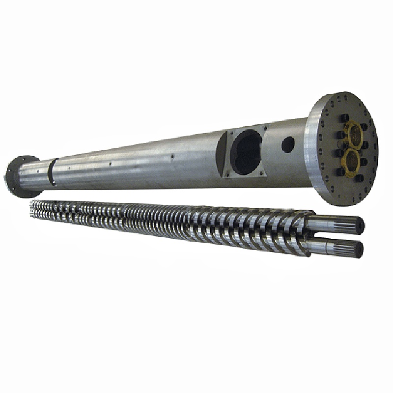
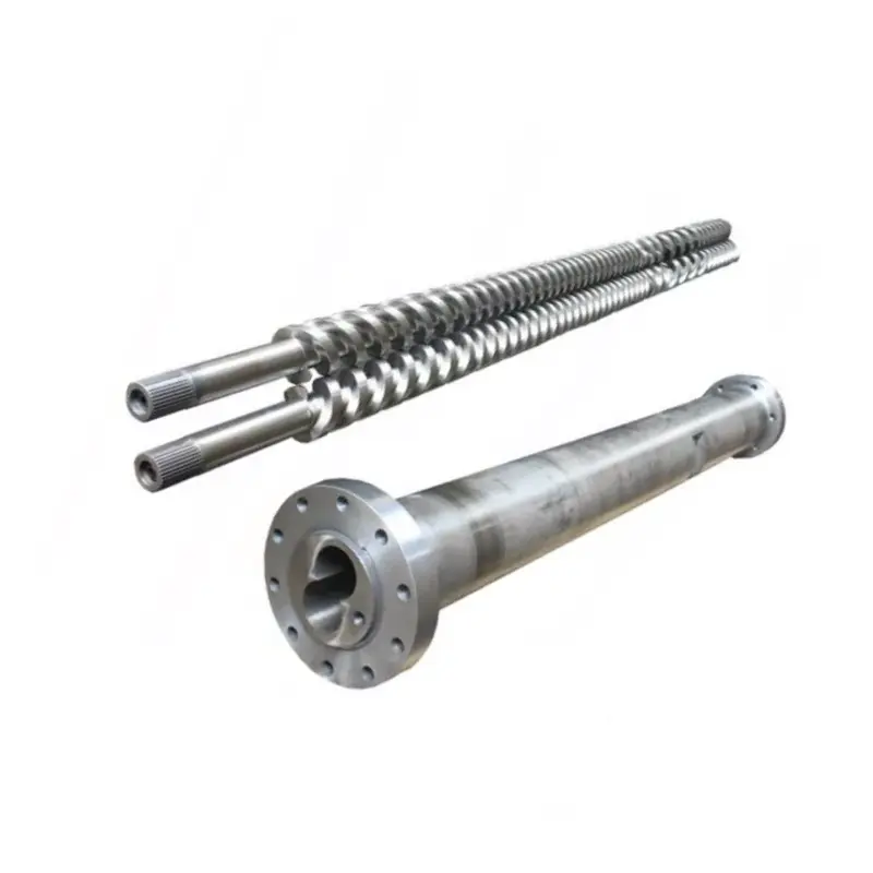
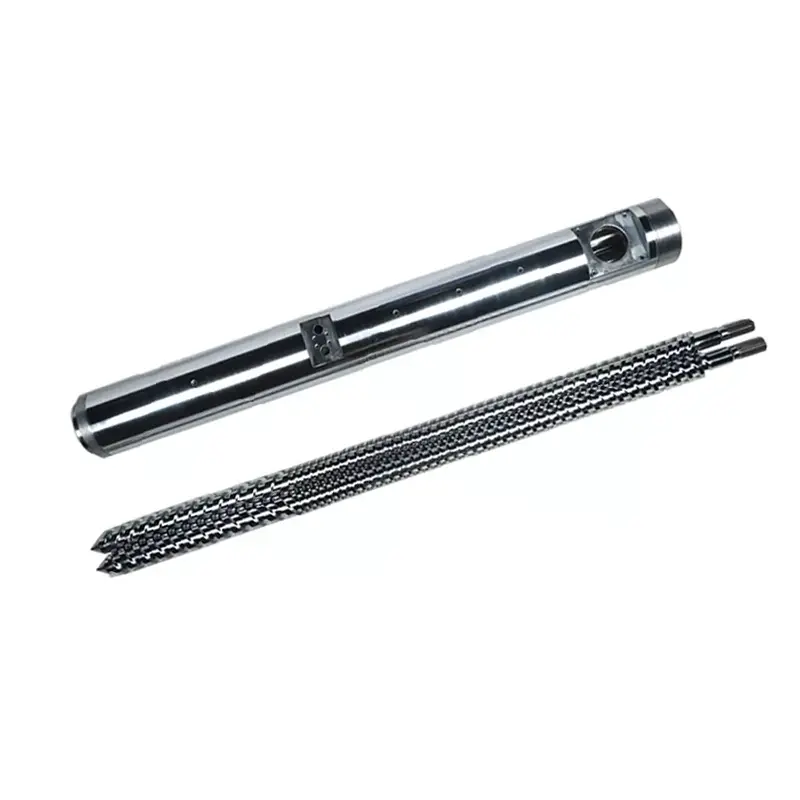
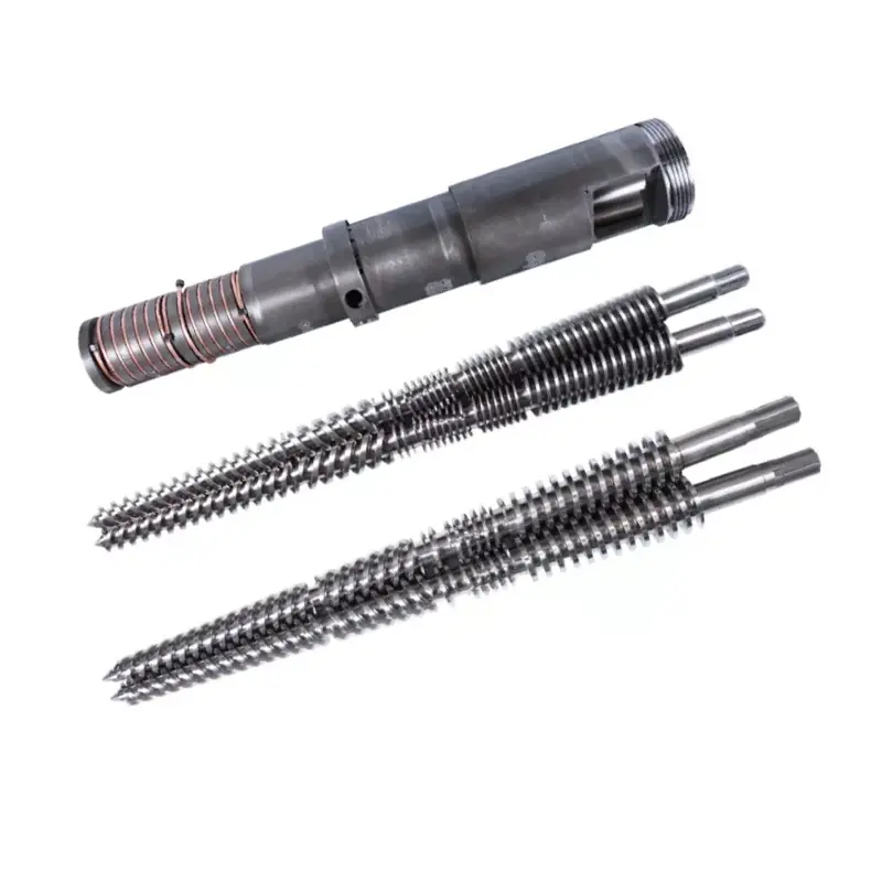
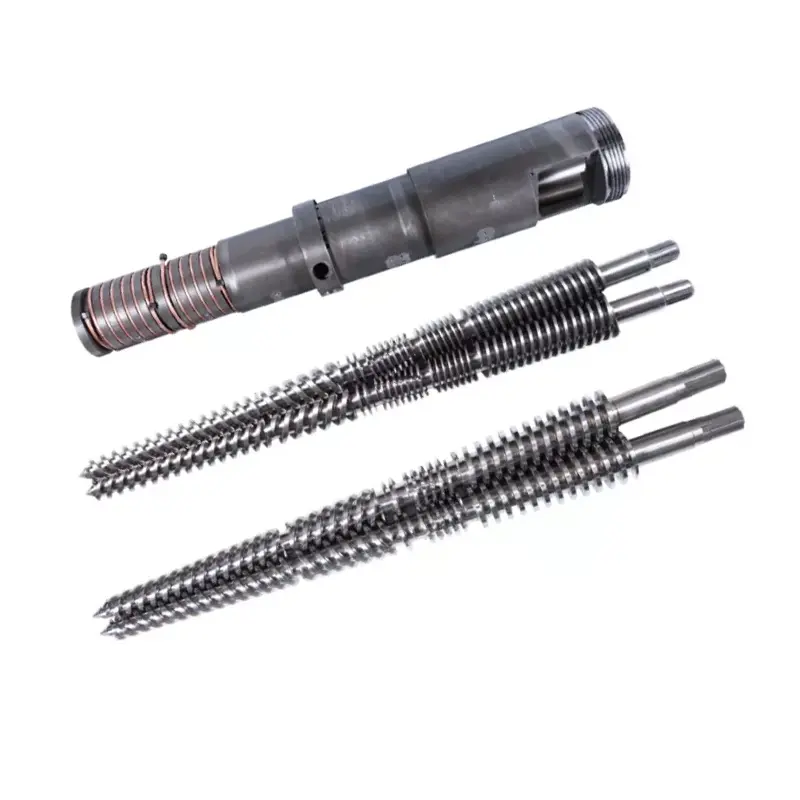
Share the associated product family so the supplier understands the system. Nanhaiya supports single screw, parallel twin screw and conical twin screw barrel applications, plus extruder confluence cores and customized die interfaces.
Machining capability supports the drawing, but does not replace it
Nanhaiya's production equipment page lists CNC drilling and milling positioning accuracy of 0.02 mm. It also identifies five-axis machining for irregular screw flights and special flange structures. These capabilities are relevant to complex hole patterns and flange features.
A machine's published positioning capability is not automatically the tolerance of every finished flange. Actual acceptance comes from the drawing, process route, fixturing, material condition, heat treatment or coating sequence and agreed inspection method.
| Manufacturing stage | Control question | Useful buyer record |
|---|---|---|
| Material receipt | Does the material match the exact grade and form stated on the order? | Material certificate when specified in the contract |
| Datum machining | Which face and axis will control later features? | Approved drawing with clear datum scheme |
| Bore and register machining | Are mating diameters, depths and fits produced in the correct sequence? | Dimensional report for critical interface features |
| Hole production | Are pitch circle, angular orientation, thread and depth referenced correctly? | Pattern inspection results and thread verification |
| Face finishing | Are seal geometry, flatness and surface requirements protected? | Specified face inspection and surface record |
| Heat or surface treatment | Will treatment change size, flatness, hardness or protected areas? | Treatment certificate and final dimensional inspection as required |
| Final marking and packing | Can the plant identify revision, orientation and mating assembly? | Part marking, inspection release and protected packaging |
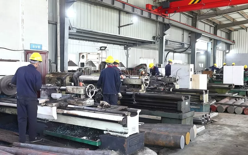
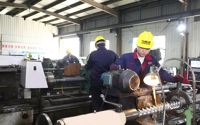
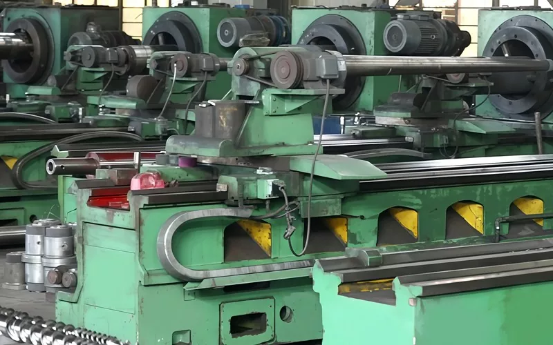
Our factory view: a tolerance should have a reason and an inspection method. We tighten locating, sealing and alignment features where the assembly needs control. Applying the smallest possible tolerance to every dimension only adds cost and can distract from the features that actually decide fit.
What common flange problems are telling you
A connection problem is rarely diagnosed by one photograph. Record when the symptom appears, whether it changes with temperature or pressure, and exactly where the leak, movement or damage begins. Change one controlled variable at a time.
| Observed problem | Possible causes to investigate | Procurement lesson |
|---|---|---|
| New flange will not enter the register | Wrong diameter or fit, coating on the locating face, burr, dirt, thermal condition or mating-part distortion | State final treated dimensions, fit, lead-in and inspection temperature |
| Bolt holes do not align | Wrong pitch circle, hole count, angular datum, handedness, thread or drawing revision | Dimension the full pattern from a visible orientation feature |
| Leak appears during heating | Thermal movement, unsuitable seal, face distortion, loss of preload or temperature outside the approved basis | Include the thermal cycle, seal specification and bolting method in the system review |
| Leak persists at one sector | Local face damage, contamination, uneven flatness, misalignment or external bending load | Specify face controls and support the attached assembly |
| Polymer degrades at the joint | Internal step, dead pocket, rough damage, leakage path or excessive residence near the interface | Control the assembled melt passage, not only the external flange dimensions |
| Fasteners repeatedly loosen or fail | Wrong fastener specification, uneven assembly, thermal cycling, vibration, overload or distorted faces | Have the responsible engineer define bolting and tightening for the complete joint |
| Corrosion begins at the connection | Unsuitable material, damaged coating, trapped contamination, incompatible environment or galvanic condition | Describe the actual chemical and cleaning environment before selecting material and treatment |
More torque is not a diagnosis. Excessive tightening can damage threads, bolts, faces, seals or connected equipment. Isolate and make the machine safe, then have qualified personnel inspect the full joint and follow the approved assembly procedure.
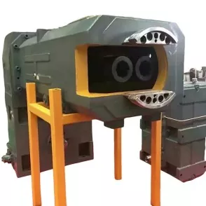
If the flange connects to a pipe extrusion die head, check the support and centerline as well as the joint. If it connects near a plastic extruder gearbox or barrel support, verify that the machine structure is not forcing the interface out of alignment.
Extruder barrel flange RFQ checklist
A complete RFQ allows the supplier to quote the same part the buyer expects to install. Attach a revision-controlled drawing whenever possible and mark every item that still needs engineering confirmation.
- Flange function and exact installation position
- Machine manufacturer, model and serial context
- Both mating component drawings or part numbers
- Outside diameter and all local envelope limits
- Central bore and internal transition geometry
- Overall thickness, hubs, steps and recesses
- Register diameters, depths, fits and lead-ins
- Bolt quantity, pitch circle and angular datum
- Clearance-hole, counterbore or thread details
- Sealing face, groove, gasket or seal specification
- Required form, orientation and position controls
- Exact material grade and heat treatment
- Surface treatment, masking and final dimensions
- Normal and design temperature information
- Normal and design pressure information
- Medium, polymer formula and cleaning exposure
- External loads, support and thermal cycles
- Applicable standard, edition and project rules
- Quantity, spare-part strategy and marking
- Material, treatment and inspection documents
- Required fit check or agreed system test
- Photos and condition report for replacements
Our factory view: photos tell us where to look, samples tell us what exists now and drawings tell us what to manufacture. A strong replacement order uses all three when available. If they disagree, we stop at drawing approval instead of choosing the most convenient measurement.
Build acceptance around the mating interface
Inspection should follow the risks identified during drawing review. A simple flat flange may need a short dimensional report. A pressure-boundary component, special adapter or close-fit replacement can require more records, witnessed inspection or system testing under the responsible engineering procedure.
| Acceptance gate | Evidence | Release question |
|---|---|---|
| Drawing approval | Signed revision with datums, dimensions, tolerances, material, treatment and notes | Does the drawing describe the intended mating assembly without relying on assumptions? |
| Material and treatment | Required certificates linked to the part or production lot | Do the records match the grade and treatment stated on the order? |
| Dimensional inspection | Results for bore, register, thickness, bolt pattern, seal geometry and specified geometric controls | Are the functional features within the approved limits after all processing? |
| Visual condition | Photos and inspection of faces, threads, coating, edges and marking | Are sealing and locating surfaces clean, protected and free of unacceptable damage? |
| Mating check | Fit with buyer-supplied mating parts, gauges or an agreed inspection fixture | Does the assembly locate, orient and fasten as intended without forcing? |
| System or pressure test | Agreed procedure, responsible approval and recorded result when required | Was the correct test performed for the flange's actual scope and governing rules? |
| Shipping release | Part identification, protection, packing list and document pack | Can the receiving plant identify, preserve and install the correct revision? |
For installation support or maintenance planning, review Nanhaiya's technical service. Supplier selection can also include the company profile, production equipment and current certificates.
Frequently asked questions
What information is required to quote an extruder barrel flange?
Send a controlled drawing or clear dimensions for the outside diameter, bore, thickness, locating register, bolt quantity, bolt-hole or thread size, pitch-circle diameter, hole orientation, sealing face and mating component. Add the extruder model, material, operating temperature and pressure basis, surface treatment, quantity and required inspection documents.
Is ANSI, DIN or JIS enough to specify a barrel flange?
No. The exact standard number, edition, size, rating, facing, material and mating component are needed for a standard pipe flange. A custom extruder or die-head flange may also require a controlled machinery drawing because its register, melt passage, bolt orientation and overall geometry can fall outside a pipe-flange standard.
What do PN6, PN10, PN16, PN25, PN40 and PN63 mean on the Nanhaiya flange page?
They are pressure-class options listed for Nanhaiya barrel flanges. They are not a universal working-pressure guarantee for every material and temperature. The purchase specification must connect the selected PN class to the exact standard, dimensions, material, temperature basis, bolting, seal and applicable system design rules.
Which material should I choose for a barrel flange?
Nanhaiya offers carbon steel, stainless steel and alloy steel options. Selection should consider load, temperature, corrosion exposure, contact with polymer or additives, welding requirements, mating-part material, surface treatment and the governing design rules. State the exact grade on the approved drawing rather than ordering only by material family.
How do I measure a replacement extruder flange?
Measure the bore, outside diameter, overall thickness, register diameters and depths, bolt quantity, hole or thread size, pitch-circle diameter, angular orientation and sealing features. Record the mating part, flow direction and assembly position. Compare the measurements with the original machine drawing because the removed part may be worn, distorted or previously repaired.
Why does an extruder flange leak after installation?
Possible causes include a damaged or unsuitable sealing face, incorrect gasket or seal, flange-face distortion, poor register alignment, contamination, uneven bolting, unsuitable fasteners, thermal movement or a pressure and temperature condition outside the approved design. Find the cause before applying more tightening force.
Can a supplier copy a worn barrel flange from a sample?
A physical sample is useful, but it should not be the only authority. Wear, corrosion, re-machining, repair and thermal distortion can change critical dimensions. Use the original drawing when available, measure the mating components and agree which dimensions will be restored before the replacement drawing is approved.
How should a custom barrel flange be accepted?
Approve the drawing first, then verify material and treatment records required by the order. Inspect the bore, register, thickness, bolt pattern, sealing geometry and specified form or position controls against the drawing. Confirm fit with the mating parts when practical, and perform only the agreed system or pressure test under the applicable engineering procedure.
Technical references
- Nanhaiya Barrel Flange: first-party materials, standards, surface treatments, PN options, applications and product images.
- Nanhaiya Production Equipment: first-party machining capabilities and published equipment positioning data.
- ASME B16.5-2020 overview: official ASME scope and contents for pipe flanges and flanged fittings.
- ISO 286-1:2010: official ISO description of the code system for tolerances on linear sizes and fits.
- ISO 1101:2017: official ISO description of geometrical tolerancing language for form, orientation, location and runout.
Standards must be purchased or accessed through their authorized publishers when their full requirements are needed. The responsible engineer should confirm the applicable edition, jurisdiction and project rules before manufacture or testing.
Editorial note: This guide separates Nanhaiya's current product options from application-specific engineering decisions. Final pressure design, bolting, sealing, material grade, tolerances and acceptance requirements must be confirmed in the approved purchase specification.