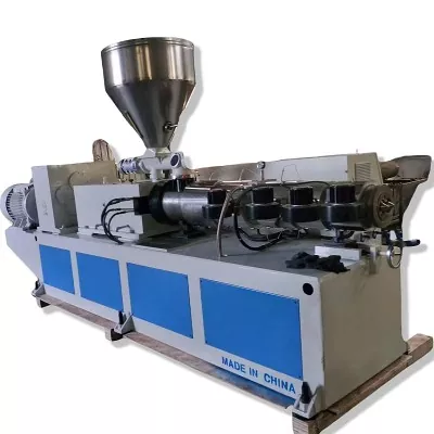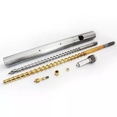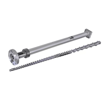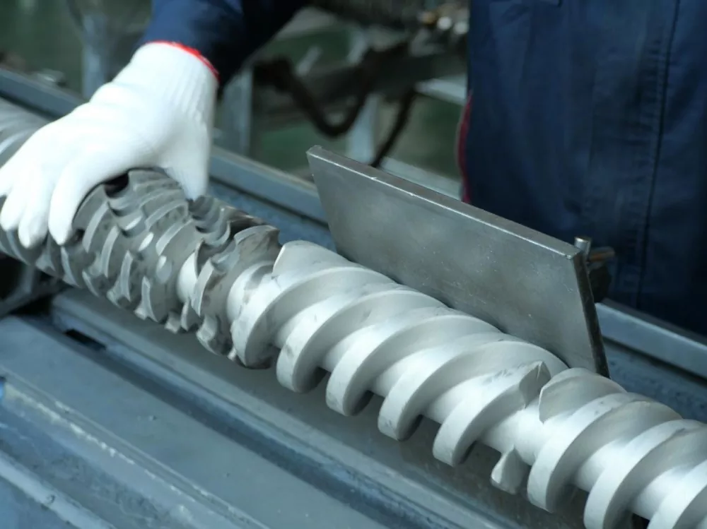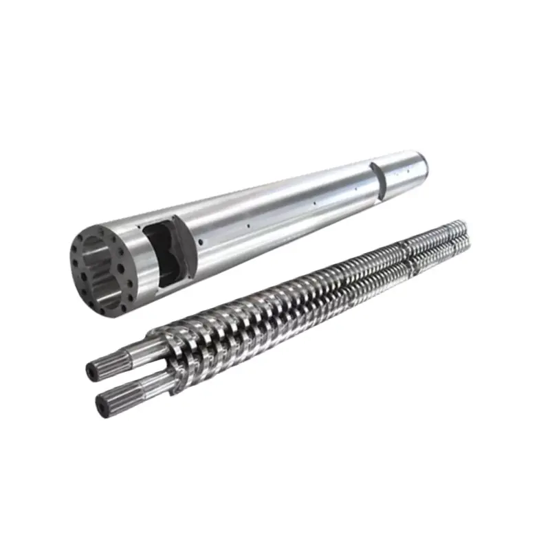

Screw rpm is not an output dial by itself. A speed change alters solids conveying, melting time, shear, pressure generation and residence time, so the useful result must be judged with melt temperature, motor load, pressure and product quality.
Quick answer
Increasing screw speed usually increases drag flow and the rate at which material enters the process, but the relationship is not unlimited or perfectly linear. More rpm can also add shear heat, shorten residence time and expose a weak feed or melting section.
Change one controlled variable at a time, wait for a stable condition, then compare output, melt temperature profile, pressure, motor load and product quality. Stop when one of those reaches its approved limit, even if the drive can turn faster.
Read the extruder as one connected system
Material enters as a bulk solid, becomes a compacted bed, melts, mixes and leaves through a restrictive flow path. The motor supplies mechanical energy while barrel heaters and cooling circuits exchange heat with the process. The screw and die share the pressure duty.
A 2016 industrial-scale study tested three polymers, three screw geometries, five speeds and three temperature conditions, for 135 operating situations. The authors measured energy demand and melt temperature variation together. Their results changed with material, screw and conditions, which is why one universal rpm-to-output rule is unreliable.
Our factory view: the best operating point is not the highest rpm the inverter accepts. It is the highest stable production condition that stays inside the approved motor, gearbox, pressure, temperature and product-quality limits. If one limit arrives early, identify that bottleneck before ordering a faster drive or a new screw.
What changes when screw speed increases
Higher rpm moves the screw surface faster relative to the barrel. In a stable range, this can increase solids transport and melt conveying. It also changes shear rate, mechanical energy input, the time available for melting and the number of screw revolutions a material experiences.
The direction of the melt-temperature change is not universal. A 2014 HDPE study used three resin viscosities, three screw geometries and several speeds and set temperatures. It found that screw type, resin viscosity, set temperature and speed all affected energy use and melt consistency.
Single-flighted screws showed a critical speed where melting quality deteriorated, while the tested barrier screw maintained better temperature uniformity.
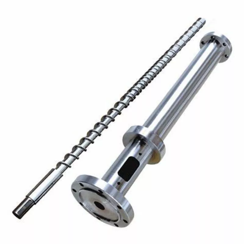
Barrel set temperature is not the melt temperature
The controller displays a heater-zone target and usually a temperature near the barrel wall. Polymer inside the channel also receives mechanical energy from deformation and friction. Cooling can remove part of that heat, but the final melt can remain hotter, colder or less uniform than one controller reading suggests.
Measure melt temperature at a defined location and state the sensor method. The 2006 Polymer Engineering & Science study used a thermocouple grid across the melt flow. It found low-temperature regions at high throughput with single-flighted screws, while the tested barrier screw with a Maddock mixer achieved better melting and lower variation.
Do not lower every heater zone just because the measured melt is hot. If the screw is creating most of the heat, an aggressive reduction can leave the solid bed colder while shear remains high. Review where melting occurs, heater output, cooling response and motor load before changing the whole profile.
Why output stops following rpm in a straight line
At lower speed, a well-fed extruder may show a near-linear relationship between rpm and mass flow. That relationship weakens when pellets no longer fill the channel proportionally, bulk density changes, the feed throat slips, melting falls behind, or downstream resistance changes the pressure-flow balance.
A 2022 University of Stuttgart study compared smooth, helically grooved and axially grooved feed zones at high screw speeds. It found a threshold beyond which throughput became nonlinear, and that pellet shape and size affected that threshold. This supports a practical factory rule: record the actual feedstock as well as the polymer name.
How to read Nanhaiya's published speed and output range
Nanhaiya publishes the following family table on both its single screw category and PE/PP high-speed page. It is useful for identifying the company's stated product range. It is not an operating guarantee for an unspecified material and die.
| Model | L/D | Published output | Published speed | Driving motor |
|---|---|---|---|---|
| NHY20 | 20:1 | 3 to 5 kg/h | 10 to 60 rpm | 1.1 / 1.5 / 2.2 kW |
| NHYZS25 | 25:1 | 5 to 8 kg/h | 10 to 60 rpm | 2.2 / 3.0 / 4.0 kW |
| NHY30 | 25:1 | 5 to 10 kg/h | 10 to 60 rpm | 2.2 / 3.0 / 4.0 kW |
| NHY45 | 25:1 to 36:1 | 10 to 120 kg/h | 10 to 150 rpm | 5.5 to 22 kW |
| NHY65 | 25:1 to 36:1 | 60 to 300 kg/h | 20 to 150 rpm | 22 to 75 kW |
| NHY75 | 25:1 to 36:1 | 200 to 450 kg/h | 20 to 150 rpm | 30 to 132 kW |
| NHY90 | 25:1 to 36:1 | 180 to 600 kg/h | 20 to 110 rpm | 30 to 185 kW |
| NHY120 | 25:1 to 36:1 | 320 to 1000 kg/h | 20 to 90 rpm | 75 to 280 kW |
| NHY150 | 25:1 to 36:1 | 400 to 1300 kg/h | 20 to 75 rpm | 90 to 400 kW |
Source: Nanhaiya website, checked August 31, 2026. Each row contains broad series values. Do not combine the highest output, speed and motor number into one assumed machine configuration.
Nanhaiya website claim: the PE/PP high-speed page states that optimized screw structure and a high-torque gearbox can double efficiency versus traditional equipment, and that its design can lower PP extrusion temperature.
The page does not state the comparison machine, resin, die, test method or acceptance window. Treat both statements as supplier claims that require a project-specific test protocol before they enter an ROI or purchase guarantee.
Interpret combinations, not isolated readings
| Trend after an rpm increase | Possible interpretation | Next check |
|---|---|---|
| Output rises, pressure and load remain stable, quality holds | The line may still be inside its useful operating window | Confirm melt-temperature uniformity and downstream cooling capacity |
| Rpm rises but output gains shrink | Feed capacity, melting or downstream resistance may be limiting | Check feed consistency, specific output, filter and die pressure |
| Melt temperature and motor load rise quickly | Mechanical energy and resistance are increasing | Review resin viscosity, screw geometry, filter condition and heat profile |
| Average melt temperature falls but variation increases | Late or incomplete melting may be present | Inspect product defects and compare with the screw's melting capacity |
| Pressure cycles with output and motor load | The problem may be feed, melting, temperature control or restriction | Use the surging diagnostic guide |
| Load rises after a filter or die change | Downstream resistance changed the operating point | Compare clean and dirty pressure at the same material and rate |

Use a controlled step test instead of chasing the controls
- Choose one stable material lot and product. Record resin grade, pellet or regrind form, additives, moisture and recent material sequence.
- Establish a baseline. Record actual rpm, feed, output, melt temperature, pressure, motor load, zone readings and product quality after the line stabilizes.
- Change one approved variable. Use the increment and stabilization time defined by the line procedure. Do not change speed, feed and temperature together.
- Compare both average and variation. An acceptable average can hide cycling pressure or an uneven melt-temperature profile.
- Mark the first limiting condition. It may be motor load, pressure, melt quality, dimensional stability, cooling capacity or surface defect.
- Repeat only inside approved limits. The useful maximum is reached when another increase gives too little output or pushes a measured condition outside acceptance.
Our factory view: a customer who sends five stable operating points gives us more useful design evidence than a customer who sends one maximum rpm. The trend shows where the line loses efficiency and whether the next change belongs in the feed section, screw geometry, wear condition or downstream equipment.
When the process trend points back to the hardware
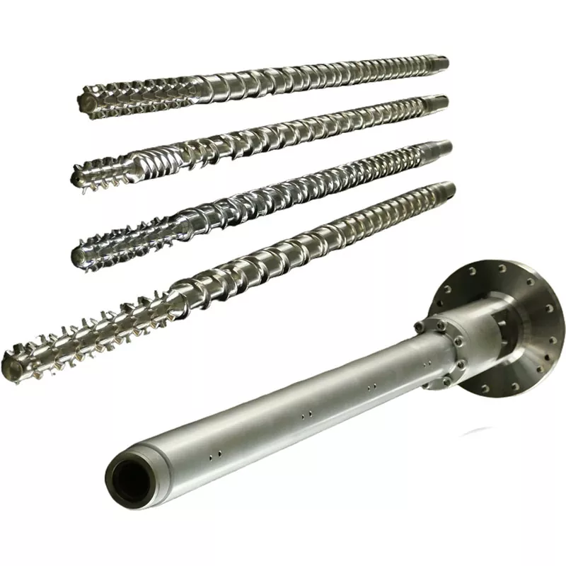
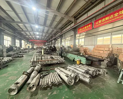
Higher rpm cannot repair excessive screw-to-barrel clearance, an undersized feed section, a melting section that falls behind, or a mixer that creates too much pressure loss. It can make those limits easier to see. Clean and measure worn components before copying them.
Use the barrier, conventional and mixing screw comparison when melt uniformity changes with speed. Use the wear measurement guide when specific output declines with a clean flow path and stable material.
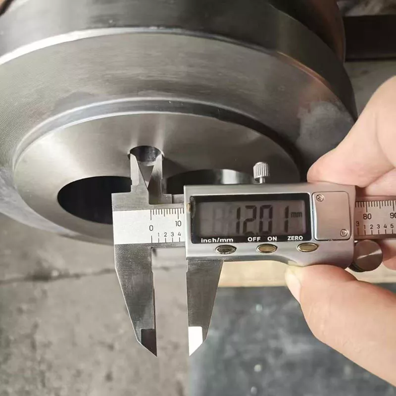
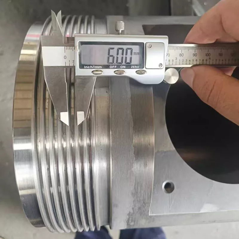
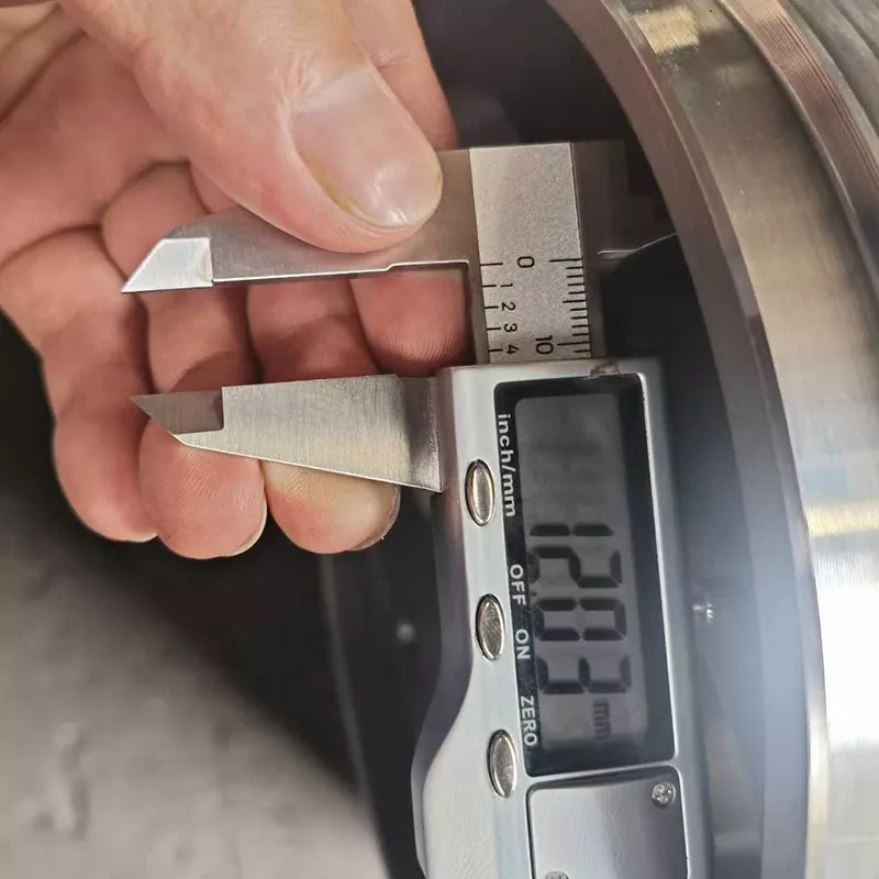
Nanhaiya's equipment page states that its CNC lathes can machine workpieces up to 6 m and its drilling and milling equipment has 0.02 mm positioning accuracy. Those are factory-level published capabilities. The approved drawing must still define the dimensions and inspection points for the order.
Data for a high-output single screw review
- Machine maker, model and screw diameter
- Original and current screw and barrel measurements
- Resin grade, pellet form, regrind and additives
- Normal and target output with accepted quality
- Motor, gearbox ratio and rated torque data
- Actual rpm, motor load and energy trend
- Barrel setpoints and actual zone readings
- Melt temperature location and sensor method
- Pressure trend, filter and die details
- Cooling, haul-off and downstream limits
- Photos of defects and retained samples
- Original drawing and connection dimensions
Frequently asked questions
Does increasing screw speed always increase extruder output?
No. Output may rise with screw speed inside a stable operating window, but feed capacity, pellet form, screw geometry, melting capacity, die resistance, motor load and wear can limit the result. At high speed, specific output can fall or the melt can become less uniform.
Is barrel set temperature the same as melt temperature?
No. Barrel setpoints control heater zones, while the polymer also receives mechanical energy from screw rotation and shear. Measure the melt at a defined location with a suitable sensor and record the method instead of treating the controller setpoint as the actual melt temperature.
Why can melt temperature rise when screw speed increases?
Higher screw speed can increase shear rate and mechanical energy input. How much the melt temperature changes depends on resin viscosity, screw geometry, fill, barrel profile and downstream resistance. Some screw and material combinations may instead show poor or incomplete melting beyond a critical speed.
Why can output stop increasing even when rpm rises?
The feed section may stop filling proportionally, pellet slip can change, bulk density can vary, melting capacity may be reached, or die and filter resistance may restrict the system. A worn screw and barrel can also increase leakage and reduce useful pumping.
What should operators record after changing screw speed?
Record actual screw speed, feed rate, output, melt temperature and variation, melt pressure and variation, motor load, zone temperatures, cooling response, product quality and the time allowed to reach a new steady condition.
What data should I send Nanhaiya for a high-output single screw review?
Send the resin grade and form, additives and fillers, required output, present rpm, motor and gearbox data, barrel profile, melt temperature and pressure trends, die and filter details, screw and barrel drawings, wear measurements and the product defect or production limit you need to solve.
Editorial note: Nanhaiya product specifications and claims are identified as company-published information. Independent research supports the process relationships, not a guarantee for any Nanhaiya model. Final limits and acceptance conditions require the material, machine, approved drawing and project test plan.