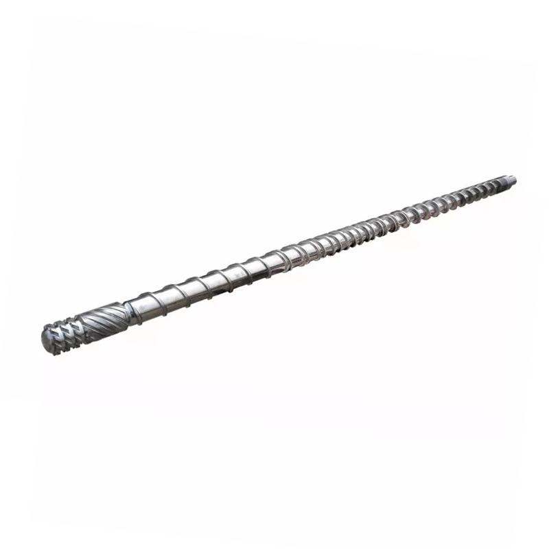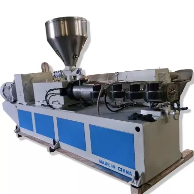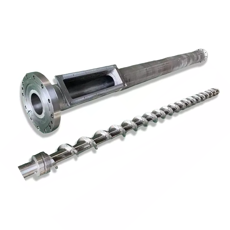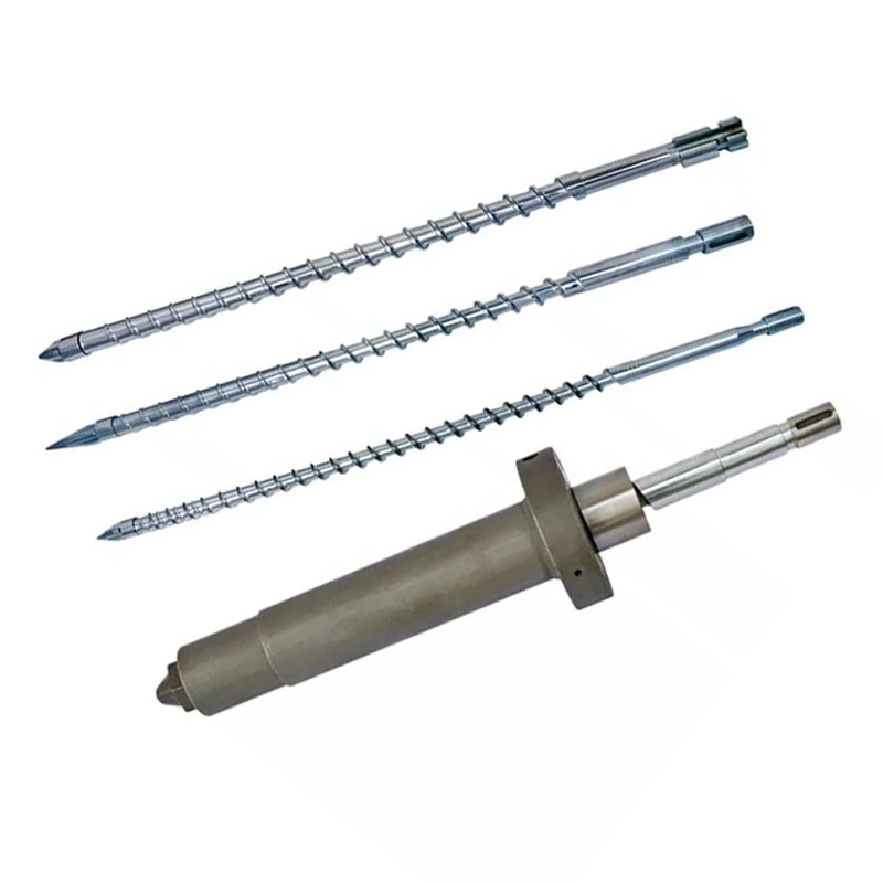

- A 3:1 ratio does not tell you whether the channels are 9 and 3 mm deep or 12 and 4 mm deep.
- L/D describes working length. Compression ratio describes a change in channel geometry.
- Material form, feeding conditions and downstream resistance belong in the same design review.
- Our transparent-granulation design pairs a 2.0:1 to 2.5:1 ratio with longer L/D and milder shear, rather than pursuing a high ratio alone.
- Before changing geometry, compare the original drawing, screw condition and matching barrel measurements.
What is extrusion screw compression ratio, and how is it calculated?
Geometric compression ratio compares the channel volume available in the feed section with that in the metering section. In a conventional, constant-lead single screw with comparable channel width and flight geometry, designers commonly use the ratio of the two channel depths. Mark A. Spalding explains the equal-lead basis in Plastics Technology.
Common depth-based expression: CR = Hf / Hm
Hf = feed channel depth; Hm = metering channel depth.
Illustrative calculation: 9 mm / 3 mm = 3.0, usually written 3:1.
Channel depth is the radial distance from the screw root to the flight outside-diameter envelope. Root diameter is a diameter, not a channel depth. If both are specified on the same cylindrical section, depth equals half the difference between flight outside diameter and root diameter. Using the full diameter difference would double the depth.
A 3:1 geometric ratio does not mean the polymer reaches three times its starting pressure or density. It describes the space the screw provides. Material transport, melting and pressure depend on the operating system. Allan Griff's SPE Extrusion Division discussion of screw dimensions makes the useful distinction between a ratio and the actual dimensions behind it.
For variable-pitch, multiple-flight or other specialized geometry, request the manufacturer's definition and the relevant channel volumes. We would not approve such a drawing by applying the simple depth formula without checking its assumptions.
Compression ratio vs L/D: which screw dimensions matter?
L/D is the screw's defined working length divided by its nominal diameter. Compression ratio compares feed and metering geometry. Changing one does not mathematically require changing the other. A longer screw can retain the same depths, while a screw of unchanged length can have a different root profile.
| Dimension | What it describes | What to request |
|---|---|---|
| Compression ratio | Feed-to-metering channel relationship | Definition plus both absolute channel depths |
| L/D | Working length relative to nominal diameter | Working-length start and end datums |
| Metering depth | Channel geometry in the final conventional zone | Depth, pitch and length, not only a ratio |
| Transition length | Distance over which channel depth decreases | Length in millimeters or clearly defined multiples of D |
| Pitch and flight width | Helical spacing and available channel width | Values and any changes along the screw |
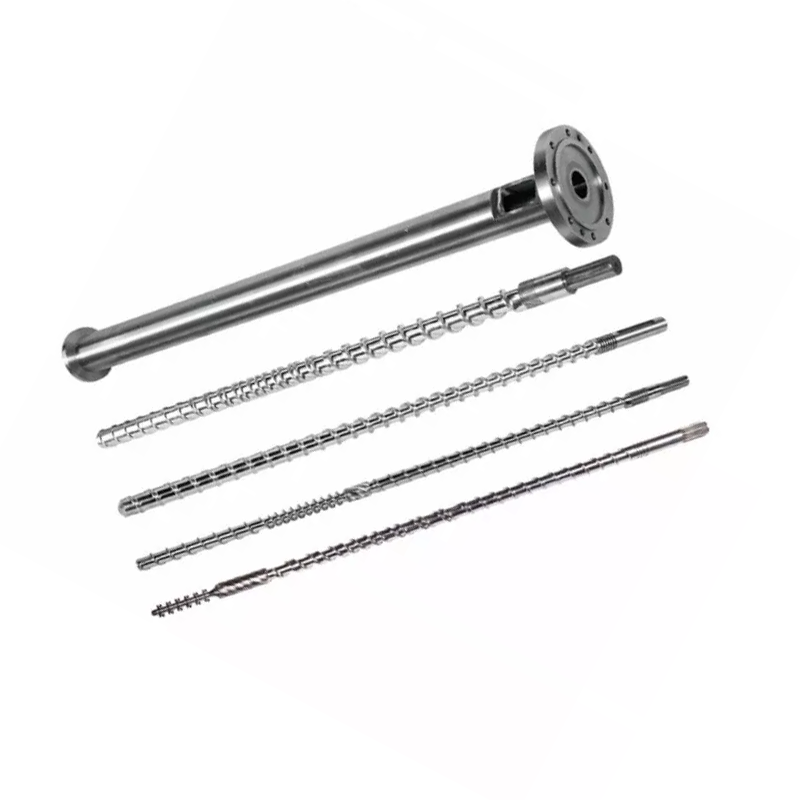
Our LDPE/HDPE film single-screw range includes L/D options of 25:1, 28:1, 30:1, 33:1 and 35:1. These are length options for different duties. They are not a table of compression ratios, and selecting 35:1 does not establish the correct feed depth.
Zone lengths also need an agreed starting point. Otherwise, two suppliers can appear to offer the same L/D while counting different portions of the component. Griff discusses working-length conventions and zone functions in his explanation of single-screw construction.
Our recommendation is to compare a dimensioned profile alongside the quotation. If the specification says only diameter, L/D and compression ratio, it still leaves the geometry open to interpretation. That is an avoidable purchasing risk, even when all three headline numbers match.
Why two 3:1 extruder screws can behave differently
Consider three illustrative conventional profiles with the same nominal diameter, equal lead in the feed and metering zones, and comparable flight geometry. All have a depth-based compression ratio of 3:1. None is automatically interchangeable with another. The examples below are geometric comparisons, not Nanhaiya product dimensions or measured production results.
| Profile | Feed depth | Metering depth | Transition length | Question raised |
|---|---|---|---|---|
| A | 9 mm | 3 mm | 6D | Baseline for this comparison |
| B | 12 mm | 4 mm | 6D | How do the deeper channels change feeding and pumping? |
| C | 9 mm | 3 mm | 10D | Does a longer transition better match the melting progression? |
In A and B, both depth pairs reduce to the same number, but B has deeper channels. The ratio therefore cannot identify the size of the feed or metering channel. In A and C, the endpoints match, but C spreads the same depth reduction over a longer distance. Its average depth reduction per unit length is lower.
Those comparisons explain why we ask for the profile rather than accepting a ratio as a complete specification. They do not prove which profile produces more good material. That decision still needs the resin, feed form, screw speed, barrel arrangement and downstream load.
On an existing machine, extra transition length must come from somewhere within the available working length. Check which zone becomes shorter and what that change means for its task. A drawing review should show the trade-off explicitly, rather than presenting a longer transition as a free improvement.
How the extruder feed barrel affects screw selection
The feed section must deliver material that the downstream screw can melt and meter. Its behavior depends on the feedstock and on contact with the screw and barrel surfaces. Spalding's analysis of solids conveying connects compression-ratio selection with resin behavior and feedstock bulk density.
For a review, describe what actually enters the hopper: pellets, regrind, flakes, a blend or a filled compound. Include changes in the proportion of those feeds. A material name such as PE does not communicate particle form or whether the feed stays consistent through a production run.
Identify the extruder feed barrel as well. A cooled, grooved feed section is a different design condition from a conventional smooth bore. Griff's discussion of grooved feeding explains why its screw geometry can differ substantially. Transferring a familiar smooth-bore ratio to a grooved-feed system without reviewing the pair is not a sound shortcut.
We would request photographs and drawings of the feed opening and any grooved insert, together with the actual cooling arrangement. These checks are more useful than increasing the quoted ratio to compensate for a feeding problem that has not been identified.
Our film product range includes a bimetallic forced-feeding single-screw configuration. When discussing that option, the question is how its feeding capability matches the required melting and metering duty. Stronger intake alone does not establish that the line can produce more acceptable film.
For a machine with unstable intake, establish a repeatable feed condition before comparing candidate geometries. Otherwise, a trial can reward a temporary material-handling change and leave the screw selection unresolved.
Choosing a plastic extruder screw for your material and product
Start with the finished product's limiting requirement. Transparent granules need a different review from film made with changing recycled content or a panel core containing additives. Our single-screw product family separates these duties because the polymer name does not fully describe the job.
| Application | Relevant Nanhaiya design information | Our selection priority |
|---|---|---|
| Transparent granulation | Production details specify 2.0:1 to 2.5:1, longer L/D and milder shear; smooth head transition and continuous grooves | Review melt uniformity and retention-prone transitions together with the ratio |
| LDPE/HDPE film | Discrete diameters from 30 to 150 mm; L/D options include 25:1 to 35:1; forced-feeding configuration | Match actual feedstock, line load and available working length before fixing depths |
| Aluminum-plastic panel core | Common diameters 65, 90, 120 and 150 mm; polished channels, rounded or torpedo head, barrier-type mixing | Consider additive distribution, flow transitions and surface selection as well as compression |
| Filled or recycled feed | PTA hardfacing on flight tops and sides; WC and nickel-based surface options | Match protection to the wear mechanism and keep the barrel in the component review |
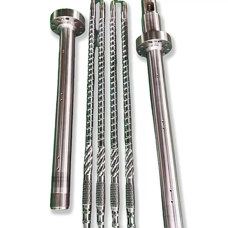
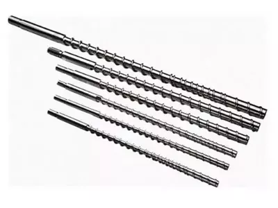
The 2.0:1 to 2.5:1 figure belongs to the application-specific production details of our transparent-granulation screw. It is not a recommendation for every transparent resin, every PS process or every machine. The linked design also addresses mixing and smooth transitions, so copying its ratio alone would leave out part of the specification.
For panel core production, our product uses a barrier-type mixing section for colorants, flame retardants and other additives. We would review that mixing duty and the formulation before recommending a more aggressive compression profile. A higher ratio does not, by itself, specify additive distribution or material compatibility.
What happens when the compression profile is too high or too low?
Both inadequate compaction and excessive feeding relative to melting capacity can cause trouble. The symptom alone does not tell you which applies. We would be cautious about either instruction, "raise the ratio to remove unmelted particles" or "lower it to reduce defects," without a dimensional and process review.
A documented PS case: more changed than the ratio
Spalding reports a 63 mm PS injection-molding plasticating screw with about 5% splay rejects. Its feed depth increased from 0.325 to 0.405 inch, while metering depth remained 0.135 inch. The ratio rose from approximately 2.4 to 3.0; the transition also lengthened by about 3.3D. The reported results were elimination of splay, an 8% shorter cycle and 14% higher plant capacity. These are the author's project results, not a Nanhaiya trial. Read the original case and geometry changes.
The useful lesson is the coordinated change. A buyer cannot reproduce that intervention by writing 3:1 on a purchase order. The feed depth and transition changed together, and the process was injection molding. Neither the percentage improvements nor the selected ratio establishes a target for a continuous extrusion line.
An extrusion counterexample
The same article describes ABS in a 6-inch, two-stage vented extruder. A first-stage ratio of 3.1 overfed the melting section, and solids plugged a spiral dam. The author proposed a new 2.5-ratio screw. The article does not report a numerical post-change output gain for that case.
Read those cases as reasons to diagnose transport and melting together. One benefited from greater compaction; the other needed a different feeding balance. Our selection rule is to identify the limiting section and preserve the conditions behind the proposed change. A defect name is not a screw specification.
Barrier and vented screws: why one overall ratio is not enough
A barrier screw separates the solids and melt paths through part of the screw. A vented screw introduces another change in channel depth and pumping duty. Reducing either design to one feed-to-final-metering ratio hides features that must appear in the review.
In a barrier section, ask how the solids channel decreases, how the melt channel develops, and what geometry controls transfer across the barrier flight. A conventional depth ratio does not describe those paths. Griff explains the distinction in his barrier-screw discussion; our guide to conventional, barrier and mixing screws connects the terminology with selection.
For a vented design, review the first stage, decompression region and downstream pumping stage separately. Ask where melting must be complete and how the second stage handles the material delivered through the vent region against the downstream resistance. The vent location belongs on the barrel drawing and the screw profile, with matching axial datums.
We would also distinguish a product's barrier-type mixing feature from a fully specified melt-extraction barrier screw. The word "barrier" on its own is not enough to establish the channel arrangement. Use a drawing to identify the feature rather than assuming every supplier uses the term for the same geometry.
These designs can be appropriate when their functions match the process. They are not automatic upgrades for every single-screw line. For a quotation comparison, require the proposed feature's location, dimensions and purpose. Otherwise, you are comparing design labels instead of solutions to the same production requirement.
Check the extruder screw and barrel before changing the ratio
A new profile should solve an identified limitation. If the line previously met its quality and output targets with the same material, gradual deterioration is a reason to inspect component condition and operating changes before deciding the original ratio was wrong.
Extruder screw wear issues that can mimic a design problem
Measure the screw and matching barrel at corresponding axial stations. Record flight diameter, bore diameter and surface condition, using an approved reference drawing where available. Our single-screw and barrel wear-measurement guide explains why a worn sample is condition evidence rather than a reliable copy of the original design.
| Observed problem | Evidence to collect first | Design question afterward |
|---|---|---|
| Output falls over time | Matched screw/barrel measurements; comparable material and operating records | Is geometry inadequate, or has the running condition changed? |
| Unmelted particles | Feed consistency, throughput, speed, melt observations and restriction history | Is intake exceeding available melting capacity? |
| Black specks after changes | Material and cleaning history; deposits and flow-transition condition | Does the proposed change address retention or only alter the ratio? |
| Pressure or motor-load cycling | Time-aligned feed, speed, temperature, pressure and load records | Which section or restriction changes first? |
This table is a collection plan, not a one-symptom diagnosis. For example, a photograph of black specks cannot identify their origin inside the screw. Keep observations separate from the proposed mechanism until inspection and operating records support the connection.
Surface specification is another separate issue. Our wear-resistant single-screw options include hardfacing on flight tops and sides. Selecting such protection does not define the correct channel profile, and changing the profile does not repair an enlarged barrel. We would resolve both questions before approving a matched replacement.
What an extruder drawing must show for a screw review
An extruder drawing should let both parties identify what stays, what changes and how the replacement fits. Alongside nominal diameter and working length, show feed and metering depths, zone lengths, pitch, flight width, mixing features, head geometry and the drive connection. Pair it with barrel bore and interface information.
How we review compression ratio before approving a screw
When we review a screw specification, we start with the material, feed condition and production problem. A request for a "65 mm screw with a 3:1 compression ratio" leaves several decisions open. We still need the actual feed and metering channel depths, transition length, screw pitch and barrel condition.
Our technical matching service considers production material, equipment model and capacity requirements alongside diameter, L/D and groove depth. That is the basis we would use for a compression-ratio review. The operating problem comes first; a preferred ratio should not predetermine the diagnosis.
For transparent granulation with black specks or unstable output, we would separate material preparation, melt quality and component condition before changing geometry. We would ask whether the change followed a resin change, cleaning or higher throughput, or appeared gradually. These observations determine which evidence to request next.
Our transparent-granulation design combines its application-specific ratio with longer L/D, milder shear and smooth flow transitions. We would examine those features together. Merely copying the ratio would leave the mixing duty, head transition and surface requirements unresolved.
The same caution applies to a worn sample. We would compare it with the approved drawing and matched barrel measurements, not treat every remaining surface as an original dimension. A 9/3 mm profile and a 12/4 mm profile are both 3:1, so a ratio cannot settle a disagreement between drawings and measurements.
Before machining, agree on retained and changed geometry, material and surface requirements, and the acceptance method. For the production comparison, record the feedstock, good output, screw speed, measured melt temperature, pressure, motor load and defect criterion. A useful result is one you can compare under defined conditions.
Send a review package that can support a decision
- Define the duty. Supply the resin grade, particle form, additives, recycled content, product and required good-output rate.
- Describe the machine. Include the machine model, drive details, screw drawing, barrel drawing and any grooved-feed or vent arrangement.
- Document the baseline. Record operating conditions and time-aligned symptoms, plus wear measurements if the parts are already in service.
- Compare a dimensioned proposal. Review both channel depths, transition length, pitch and special features, stating the reason for each change.
- Agree on acceptance. Define dimensional inspection and production-comparison conditions before approving manufacture.
Discuss your screw profile with Nanhaiya
Send the profile, material details and current production problem to Zhoushan Nanhaiya Plastic Machinery Co., Ltd. We can review the relevant single-screw application and parameter-matching requirements with you.
Request a screw specification review
Email: info@nhyscrew.com
Phone: +86-13505809643
Frequently asked questions
How do you calculate extrusion screw compression ratio?
For a conventional single screw with the same lead in the feed and metering zones and comparable flight geometry, the common depth-based expression is feed channel depth divided by metering channel depth. A 9 mm feed depth and 3 mm metering depth give 3:1. For specialized geometry, confirm the channel-volume definition rather than assuming the depth shortcut applies.
Is compression ratio the same as L/D?
No. Compression ratio describes the feed-to-metering channel relationship. L/D is working length divided by nominal screw diameter. They answer different questions, so a screw quotation should state both and define the working-length datums. Neither number replaces the actual channel depths and zone lengths needed to review the geometry.
Does a higher compression ratio always improve melting?
No. A ratio must suit the feeding, melting and metering balance. Increasing it can change feeding capability without resolving the limiting section. Before choosing a higher value, review how the proposed dimensions change the process, including transition length and any downstream mixing restriction. Compare acceptable output and melt quality, not the ratio alone.
Can the same polymer require a different screw when the feedstock changes?
Yes. Pellets, regrind, flakes and filled blends are different feeding conditions even when they share a polymer name. Supply the actual feed form, composition and consistency during the review. A previous screw's performance with one feedstock does not establish that its compression profile will suit another.
Can changing screw speed change the geometric compression ratio?
No. Screw speed changes an operating condition, not the machined channel geometry. It can change the line's feeding, melting and pumping behavior, so speed belongs in the production baseline and trial record. Raising or lowering rpm does not turn a 2.5:1 depth profile into a 3:1 profile.
What information is missing from an order for a 3:1 screw?
The order still needs actual feed and metering depths, diameter, working length, transition length, pitch, flight geometry and any mixing or vented features. It also needs drive and barrel compatibility, material and surface requirements, and the intended production duty. Without these details, several different screws could satisfy the same 3:1 description.