
An extruder gearbox does more than reduce motor speed. It must transmit the required torque, support the correct shaft arrangement, manage heat and lubrication, and fit the existing screw, coupling, housing and foundation. This guide turns those duties into a practical RFQ and acceptance plan.
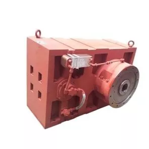
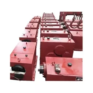
Quick answer
To buy a plastic extruder gearbox, specify the motor power and rated speed, required screw-speed range, continuous and peak torque duty, screw quantity and rotation, material and output, operating hours, input and output shaft interfaces, mounting position, thrust load, lubrication, cooling and acceptance test.
Motor power alone is not a gearbox specification. Two lines with the same motor can impose different torque, heat, shock, synchronization and bearing duties. The signed drawing should identify the motor-side shaft and screw-side shaft, their speeds, rotation directions, ratio, mounting datums and every connection needed for installation.
Define the gearbox job before comparing models
The gearbox sits between the motor and the screw system. It changes speed and torque, but it also keeps the drive geometry stable under process load. On a twin-screw line, it must distribute power to two shafts and preserve the required rotation relationship.
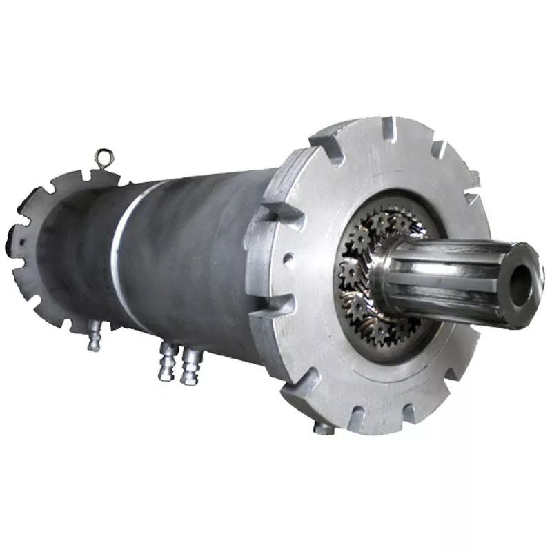
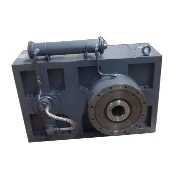
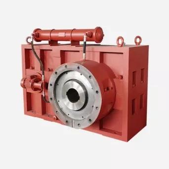
Nanhaiya offers extruder gearboxes for twin-screw extruders and other plastics-processing equipment. Listed applications include PVC and WPC production, PP and PE profiles, pipes, pellets, rubber processing, chemical production and compounding.
| Buyer input | Why it changes the gearbox | Evidence to send |
|---|---|---|
| Extruder type | Sets the number of output shafts, rotation relationship, center distance and thrust arrangement | Machine model, general arrangement and screw configuration |
| Material and formulation | Changes steady torque, torque peaks, start-up load and process stability | Resin grade, filler, moisture, recycled content and representative sample |
| Required output | Links gearbox duty to actual production rather than an unloaded screw speed | Stable saleable kg/h by product and material |
| Motor | Defines available power, rated speed, frame, coupling and control range | Nameplate, motor curve, drive method and dimensional drawing |
| Screw-speed range | Sets the operating ratio and affects torque, heat and bearing speed | Minimum, normal and maximum r/min under load |
| Operating schedule | Separates intermittent duty from continuous production and frequent starts | Hours per day, starts, reversals, cleaning and material changes |
| Environment | Affects seals, cooling, oil temperature, corrosion protection and enclosure | Ambient range, dust, water, altitude and installation area |
Our factory view: we do not start a replacement gearbox from the motor kilowatts printed on the nameplate. We start with the screw duty and work backward through the shaft, bearings, gears, ratio and motor. This exposes overload and interface questions before the housing is machined.
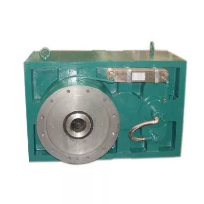
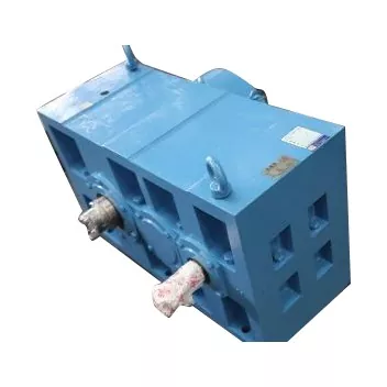
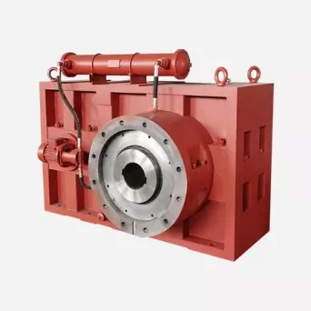
What Nanhaiya currently lists for its extruder gearbox
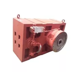
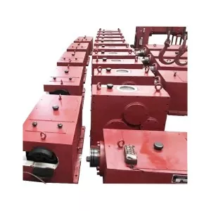
The current product configuration uses a steel gearing arrangement and lists a weight of 100 kg. It is intended for plastic and rubber machinery, including PVC and WPC profile and pipe extruders. Export packing is a wooden case.
The range supports multiple structures, installation directions and connection options. Oil cooling and forced lubrication are available. The product listing also includes a two-year warranty, outgoing video inspection, a machinery test report and a stated supply ability of 500 sets per month.
| Published field | Current Nanhaiya listing | What to lock in the purchase order |
|---|---|---|
| Material and part type | Steel, gearing arrangement | Housing, shaft, gear and heat-treatment specifications for the quoted model |
| Application | PVC and WPC profile and pipe extruder; plastic and rubber machinery | Exact extruder, material, output and duty cycle |
| Input speed | 8 to 100 r/min | Identify which physical shaft this field describes |
| Output speed | 300 to 1500 r/min | Identify which physical shaft this field describes |
| Weight | 100 kg | Final drawing weight, lifting points, foundation and shipping scope |
| Lubrication and cooling | Forced lubrication and oil cooling available | Oil, pump, filter, cooler, instruments, piping and utility boundary |
| Inspection documents | Outgoing video inspection and machinery test report provided | Report content, operating condition, measured points and acceptance limits |
| Warranty | Two years | Start date, covered parts, exclusions, labor, freight and claim procedure |
| Supply and packing | 500 sets per month; export wooden case | Quoted quantity, confirmed lead time, preservation and packing standard |
Label both shafts, not only "input" and "output." Our current product table lists 8 to 100 r/min as input and 300 to 1500 r/min as output. Before ordering, mark the motor-side shaft and screw-side shaft on the drawing, then confirm the speed, torque and rotation of each. This removes any naming ambiguity.
Convert power and speed into a real torque duty
Power tells only part of the drive story. At the same transmitted power, torque rises as shaft speed falls. The simple relationship below helps a buyer check units and understand why a low-speed extrusion shaft can create a demanding gearbox duty.
This equation is a starting check, not a complete gearbox rating. The manufacturer still needs transmission efficiency, load spectrum, starts, shock, reversals, overload duration, temperature, gear geometry, materials, bearings and the applicable design method. Use the actual power transmitted at the shaft, not an assumed full motor nameplate value in every condition.
| Torque input | Question to answer | Why it matters |
|---|---|---|
| Continuous operating torque | What torque is carried during stable saleable production? | Sets the main thermal and fatigue duty |
| Peak process torque | What occurs with difficult feed, high fill, pressure change or a temporary upset? | Checks short-duration gear, shaft and bearing capacity |
| Starting torque | Can the line start loaded, or must the screw be empty? | Changes the start sequence and peak duty |
| Torque per output shaft | How is total torque divided on a twin-screw drive? | Prevents total motor torque from being confused with each shaft's duty |
| Load spectrum | How many hours are spent at each load and speed? | Supports gear and bearing rating for the actual production schedule |
| Permitted overload | How high, how long and how often? | Turns the word "overload" into a measurable condition |
Our factory view: "high torque" is not an inspectable requirement. We want a torque value, shaft speed, duration, frequency and material condition. Once those are defined, the phrase can be replaced by a rating calculation and an agreed operating boundary.
The same system logic applies to process tuning. Our guide to screw speed, melt temperature and output explains why higher r/min does not guarantee stable production. A gearbox must support the useful process window, not only the highest speed available from the drive.
A twin-screw gearbox is not a single-screw reducer with another shaft
A single-screw extruder has one driven screw shaft. The gearbox must match that shaft, transfer the process thrust through the intended bearing path and keep the barrel and screw aligned. Replacement work focuses on the one output interface and its relationship to the barrel centerline.
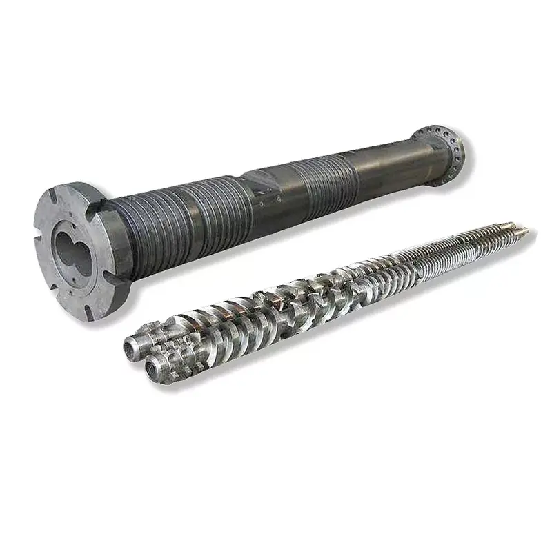
A twin-screw extruder adds power splitting and synchronization. Nanhaiya's twin-screw machine uses a high-torque gearbox and is offered with conical or parallel screw structures for PVC, WPC, granulation and related processing. The drive specification must match the exact screw geometry and rotation mode.
| Drive question | Single screw | Twin screw |
|---|---|---|
| Output shafts | One screw output | Two outputs with a defined center distance |
| Rotation | One direction relative to the barrel and die | Co-rotating or counter-rotating relationship plus viewed direction |
| Torque definition | Torque at the single output shaft | Total drive torque and allowable torque at each output shaft |
| Synchronization | Not a two-shaft requirement | Gear relationship must maintain the intended screw phasing |
| Output interface | One spline, key, coupling or shaft connection | Two matched interfaces, axial positions and assembly sequence |
| Thrust handling | One process-thrust path | Two shaft loads and the specified thrust-bearing arrangement |
| Replacement evidence | One shaft drawing plus housing and barrel datums | Both shafts, center distance, phase, rotation, barrel bores and complete assembly drawing |
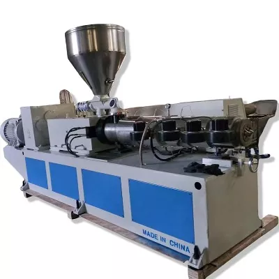
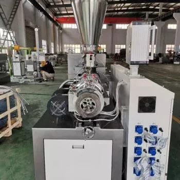
If the line compounds filled or recycled materials, include the real formulation and feed condition. Nanhaiya's parallel twin-screw pelletizing line is intended for mixing, dispersing and devolatilizing duties. These process loads can differ from a line that runs clean resin at a steady rate.
Confirm ratio, speed range and rotation on one drawing
The nominal ratio connects motor speed to screw speed, but the useful operating range also depends on the motor and variable-frequency drive. A ratio that reaches the requested maximum r/min may leave poor motor operation or insufficient torque at the normal production point.
List at least four speed conditions: inching or maintenance speed if provided, minimum stable process speed, normal production speed and maximum approved screw speed. For each condition, state motor speed, gearbox input speed, gearbox output speed, torque and the material being processed.
Use viewed directions. "Clockwise" is incomplete unless the drawing says which shaft is observed and from which end. Add rotation arrows to the input and every output shaft, then confirm the relationship during the outgoing test.
| Drawing field | What to show | Common mistake |
|---|---|---|
| Motor-side shaft | Speed range, torque, rotation, shaft or flange and coupling | Using motor rated speed without the actual drive range |
| Screw-side shaft | Required r/min, continuous torque, peak torque and interface | Quoting screw speed without the load condition |
| Nominal ratio | Exact ratio and any tolerance or measured report required | Rounding the ratio and assuming the screw speed will remain exact |
| Rotation direction | Arrow, viewed end and twin-shaft relationship | Writing only CW or CCW |
| Control boundary | Motor, VFD, encoder, interlocks and low-speed limits | Treating the mechanical gearbox and electrical drive as unrelated purchases |
Our factory view: we prefer the motor-side and screw-side terms on replacement drawings. They remain clear even when an old nameplate, translation or supplier catalog uses input and output differently. The rotation arrows then remove the last easy source of misunderstanding.
Control the interfaces before the replacement housing is cast or machined
A correct ratio does not make a replacement gearbox interchangeable. The shaft form, spline or key, coupling, center height, mounting feet, bolt pattern, barrel connection, thrust assembly, lubrication ports and service clearances must all fit the existing machine.
- Input shaft diameter, length, key or spline
- Motor flange, frame, coupling and guard
- Output shaft quantity and center distance
- Output spline, key, bore or coupling drawing
- Output shaft axial position and permissible movement
- Screw thrust direction and load path
- Housing footprint and mounting-bolt pattern
- Input and output center height from foundation
- Barrel, adapter and support interfaces
- Rotation direction viewed from a stated end
- Oil fill, drain, level and sampling access
- Pump, filter and cooler connections
- Temperature, pressure, flow and vibration sensors
- Breather, seals and leakage collection
- Lifting points and component weight
- Maintenance space for covers, shafts and filters
For an existing line, send the original general-arrangement drawing and fresh measurements. A failed sample can be worn, repaired or built to an earlier revision. Measure the mating motor, coupling, screw shafts, barrel support and foundation instead of copying only the removed gearbox.
Do not use coupling flexibility to hide bad alignment. Record motor shaft, gearbox shaft and screw centerlines from controlled datums. Confirm soft foot, foundation condition and installed alignment through the applicable machine and coupling procedure.
Specify the lubrication and cooling system as equipment
Nanhaiya offers oil cooling and forced lubrication for different operating conditions. These are not isolated accessories. The pump, oil, filter, cooler, pipework, instrumentation and controls must deliver the required condition throughout start-up, stable production and shutdown.
ISO 12925-1:2024 covers lubricant specifications for enclosed gear systems. It provides a useful framework for lubricant categories, while the gearbox manufacturer must still select the correct oil for the gears, bearings, seals, temperature and service conditions.
| Lubrication item | What to define | Why buyers should ask |
|---|---|---|
| Oil specification | Approved lubricant category, viscosity grade and compatible alternatives | Wrong viscosity or additive chemistry can affect film, temperature and seals |
| Delivery method | Splash, forced circulation or combined system for the quoted arrangement | Mounting position and speed change where oil reaches |
| Pump | Flow, pressure, motor, duty and standby requirement | Forced lubrication depends on verified delivery, not pump presence alone |
| Filter | Rating, indicator, bypass logic, replacement element and access | Contaminated oil can damage gears and bearings |
| Cooler | Heat duty, cooling medium, inlet condition and fouling allowance | A cooler must match the plant water or air condition |
| Instruments | Oil temperature, pressure, flow, level and alarm or trip points | Operators need evidence before a lubrication fault becomes damage |
| Service procedure | Fill quantity, sampling point, change method, flushing and storage | Maintenance errors can contaminate a clean gearbox |
State the utility boundary clearly. If the buyer supplies cooling water, list temperature, flow, pressure, quality and connection. If the package uses air cooling, show clearance and ambient limits. The controls should prevent loaded operation when required oil flow or pressure is absent.
Our factory view: a lubrication skid should be treated like part of the gearbox, not a loose collection of purchased items. We want to know how the oil reaches the loaded gears and bearings, how the operator sees a fault and what condition stops the drive.
Ask how the gears, bearings and vibration limits are rated
A purchasing specification should name the design basis instead of requesting "good gears" or "long bearing life." ISO 6336-1:2019 gives principles and influence factors for calculating the load capacity of spur and helical gears. The ISO page also states that the method compares gear designs and does not assure the performance of an assembled drive system by itself.
ISO 1328-1:2013 provides a tolerance-classification system for the tooth flanks of individual cylindrical involute gears. A class number is useful only when the quotation identifies the standard, edition, applicable gear, inspection scope and report.
For rolling bearings, ISO 281:2007 covers basic dynamic load ratings and rating life. Its modified-life method can account for reliability, lubrication, contamination and fatigue load. The standard does not cover wear, corrosion or electrical erosion, so bearing selection still needs the real shaft load and environment.
| Technical area | Useful reference | Procurement question |
|---|---|---|
| Cylindrical-gear capacity | ISO 6336 series where applicable | Which parts, edition, load spectrum, factors and failure modes were used? |
| Gear-flank tolerances | ISO 1328-1 where applicable | Which gears, tolerance class, measured parameters and report are included? |
| Rolling-bearing rating life | ISO 281 where applicable | What radial and axial loads, speed, reliability, lubrication and contamination assumptions were used? |
| Enclosed-gear lubricant | ISO 12925-1 where applicable | Which lubricant category and viscosity does the manufacturer approve? |
| Gear-unit vibration | ISO 20816-9 within its scope | Where, under what load and speed, with which instrument and against what agreed grade? |
ISO 20816-9:2020 covers vibration measurement and evaluation for individually housed enclosed gear units within its stated power and speed range. It includes factory acceptance and can support agreed site or routine measurements. It applies within the unit's design speed, load, temperature and lubrication range, so a no-load reading is not the same as a production-load result.
Operating symptoms help locate the problem before replacement
Noise, heat and vibration can come from the gearbox, but they can also enter through the motor, coupling, foundation, screw or process load. Record the condition before opening the unit. A short video without speed, load and temperature data rarely identifies the cause.
| Observed symptom | Checks to make first | What the finding may change in the next RFQ |
|---|---|---|
| Oil temperature rising | Oil type and level, flow, filter, cooler, ambient, load, speed and internal losses | Cooling duty, instrumentation, lubricant, ratio or load rating |
| New or changing noise | Load relation, gear-mesh frequency, bearings, coupling, foundation and lubrication | Gear tolerance, bearing arrangement, alignment control or test scope |
| High housing vibration | Measurement location, speed, load, foundation, soft foot, alignment and connected-machine vibration | Mounting stiffness, site alignment, acceptance points and limits |
| Oil leakage | Seal surface, breather, oil level, pressure, shaft movement, housing joint and installation angle | Seal arrangement, venting, shaft finish or mounting orientation |
| Motor current increases | Material, feed, die pressure, screw contact, bearings, oil condition and gearbox damage | Torque duty, overload definition, screw condition or process correction |
| Output becomes unstable | Feed consistency, screw speed, coupling, backlash, control signal, melt pressure and mechanical damage | Drive control, process window, inspection or replacement scope |
| Metal appears in the oil | Particle type and source, gears, bearings, housing damage, filter and maintenance history | Immediate inspection plan, material, filtration and condition monitoring |
Do not keep running to make the symptom easier to hear. Follow the plant and equipment manufacturer's safe shutdown, pressure-release and energy-isolation procedure. Hot oil, rotating shafts, stored pressure and heavy covers require trained personnel and an approved maintenance plan.
Check the screw and barrel before blaming the drive. Our single-screw wear measurement guide explains how uneven clearance, alignment or metal contact can create load symptoms that reach the gearbox. Twin-screw lines also need center-distance and clearance checks against the correct drawings.
Our factory view: a failure report should describe what changed and what stayed normal. We ask for motor current, screw speed, material, output, oil temperature, vibration location and time history. That evidence separates process overload from lubrication, alignment and internal transmission problems.
Plastic extruder gearbox RFQ checklist
Use this checklist for a new machine or a replacement. Mark unknown items instead of filling the gaps with an assumed value. The supplier can then identify which measurements or calculations are still required.
- Extruder make, model and serial context
- Single, parallel twin or conical twin screw
- Co-rotating or counter-rotating relationship
- Screw diameter, center distance and shaft drawings
- Material, formulation and feed condition
- Normal and maximum saleable output
- Motor power, rated speed and frame
- VFD or servo operating-speed range
- Minimum, normal and maximum screw speed
- Continuous torque at each output shaft
- Peak torque, duration and frequency
- Starting method and loaded-start condition
- Daily hours, starts, stops and reversals
- Input shaft, flange and coupling drawing
- Output shafts, splines, keys or couplings
- Thrust direction, load and bearing boundary
- Foundation, footprint and center height
- Mounting direction and surrounding clearances
- Ambient, dust, water and altitude conditions
- Lubricant, pump, filter and cooler scope
- Cooling-water or air utility condition
- Temperature, pressure, flow and vibration sensors
- Control signals, alarms, trips and interlocks
- Gear and bearing rating standards
- Required material and inspection documents
- Outgoing test condition and acceptance limits
- Spare parts, tools and maintenance manuals
- Warranty scope and service responsibility
Our factory view: the best replacement package contains the old nameplate, original drawing, fresh interface measurements and operating history. The nameplate identifies what was supplied. The measurements show what is installed. The history explains why the plant is replacing it.
Agree on the test condition before the gearbox is built
Nanhaiya provides outgoing video inspection and a machinery test report for the current gearbox product. The RFQ should define what the report contains. A video of a rotating shaft proves rotation, but it does not by itself prove torque capacity, temperature stability or production performance.
| Acceptance gate | Evidence | Question to resolve |
|---|---|---|
| Document review | Approved general arrangement, shaft drawings, nameplate schedule, lubrication schematic and parts list | Does every interface match the purchased scope and revision? |
| Material and component records | Agreed certificates and identification for gears, shafts, bearings and housing | Do the records match the quoted design? |
| Dimensional inspection | Mounting, center height, shaft, spline, bolt pattern, center distance and connection results | Will the unit fit without field machining? |
| Rotation and speed | Input and output r/min plus viewed rotation direction | Do ratio and direction match the screw system? |
| Lubrication function | Oil level, pressure, flow, filter and cooler operation | Does the system operate through the agreed test range? |
| Temperature and leakage | Oil and bearing temperatures, test duration and visual record | Was the unit stabilized under the stated speed and load? |
| Vibration and sound | Measurement points, instrument, speed, load and agreed limits | Are the readings comparable with the named procedure? |
| Protection test | Alarm, trip and interlock simulation where included | Does the drive respond correctly to loss of oil flow or excessive temperature? |
| Shipping release | Preservation, oil status, loose items, spares, documents and wooden-case packing | Can the plant store, lift and install the unit without losing identification? |
State whether testing is no-load, shop-load or performed on the complete extrusion line. If the full production load cannot be reproduced at the gearbox factory, separate the shop inspection from the site commissioning test. Identify who supplies material, utilities, instruments and acceptance authority.
Nanhaiya's service program includes requirement diagnosis, parameter matching, installation guidance and maintenance advice. Final warranty, commissioning and response obligations should be written into the contract for the specific gearbox order.
Frequently asked questions
What information is needed to quote a plastic extruder gearbox?
Send the extruder type, screw quantity and rotation, motor power and rated speed, required screw-speed range, continuous and peak torque duty, material and output, operating schedule, input and output shaft drawings, center distance, thrust-load arrangement, mounting position, lubrication and cooling requirements, utilities, ambient conditions and an agreed test plan.
How do I choose the gearbox ratio for an extruder?
Start with the motor operating-speed range and the required screw-speed range. The ratio must keep the motor and screw within their approved torque and speed envelopes across normal production, start-up and difficult material conditions. Confirm the exact input shaft, output shaft, rotation direction and any variable-frequency drive range on the approved drawing.
What do Nanhaiya's published input and output speeds mean?
Nanhaiya's current plastic extruder gearbox listing gives an input speed of 8 to 100 r/min and an output speed of 300 to 1500 r/min. Because shaft naming conventions can differ, the purchase drawing should label the motor-side and screw-side shafts directly, then state the speed of each shaft, the ratio and the rotation direction.
Is a twin-screw extruder gearbox different from a single-screw gearbox?
Yes. A single-screw drive has one output shaft, while a twin-screw drive must distribute power to two shafts and maintain the required rotation relationship and center distance. The twin-screw specification must also define torque per shaft, synchronization, output-shaft interfaces and the thrust-load path for the exact extruder.
When does an extruder gearbox need forced lubrication or oil cooling?
The gearbox designer selects the system from transmitted power, speed, load cycle, ambient temperature, allowable oil temperature, mounting position and internal loss. Nanhaiya offers oil cooling and forced lubrication options. The final package should state oil specification, pump, filter, cooler, instruments, alarm logic and required utilities.
Which standards are useful when specifying an extruder gearbox?
Depending on the design and project, useful references can include ISO 6336 for cylindrical-gear load-capacity calculations, ISO 1328-1 for gear-flank tolerance classification, ISO 281 for rolling-bearing rating life, ISO 12925-1 for enclosed-gear lubricants and ISO 20816-9 for vibration evaluation within its stated scope. The quotation must name the exact standards and editions actually used.
What should be checked before an extruder gearbox is shipped?
Approve the interface and nameplate data first. The agreed inspection can then cover rotation direction, input and output speed, oil flow and pressure, leakage, bearing and oil temperature, vibration, sound condition, shaft runout, protective devices and document review. State whether the test is no-load, shop-load or on the complete extrusion line.
Should a noisy extruder gearbox be repaired or replaced?
Do not decide from noise alone. Record speed, motor current, load, oil temperature, vibration, oil condition, leakage and when the sound appears. Inspect alignment, coupling, foundation, lubrication, bearings and gears under the approved maintenance procedure. Compare the repair scope, parts availability, downtime and remaining interface condition before choosing repair or replacement.
Editorial note: Product details and images come first from Nanhaiya's current website. Application-specific ratings, shaft labels, standards, limits and test conditions must be confirmed in the signed quotation and approved drawings for the actual gearbox.