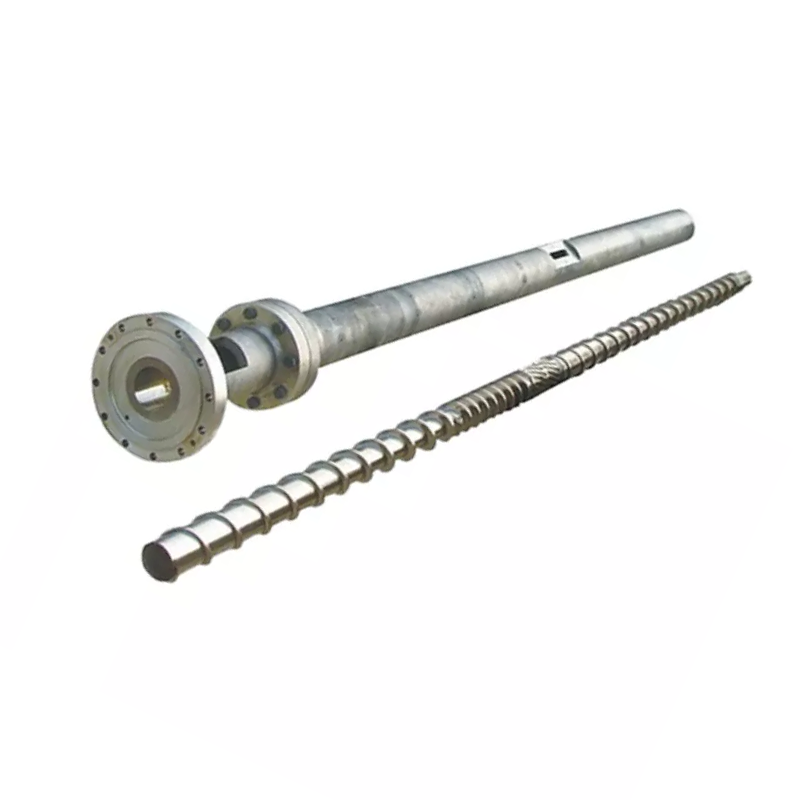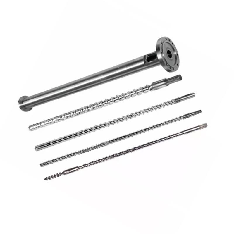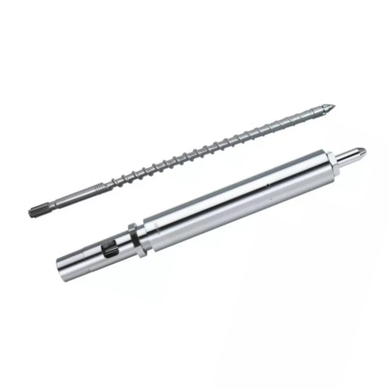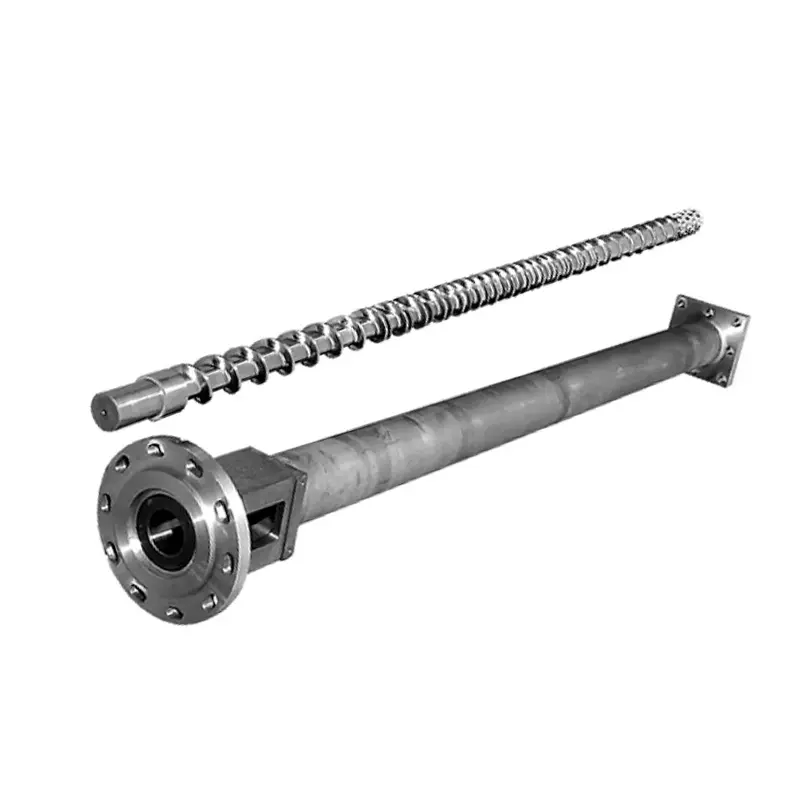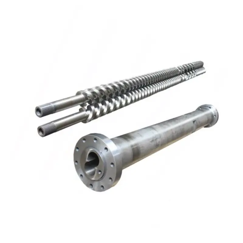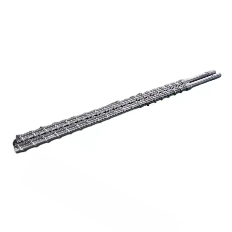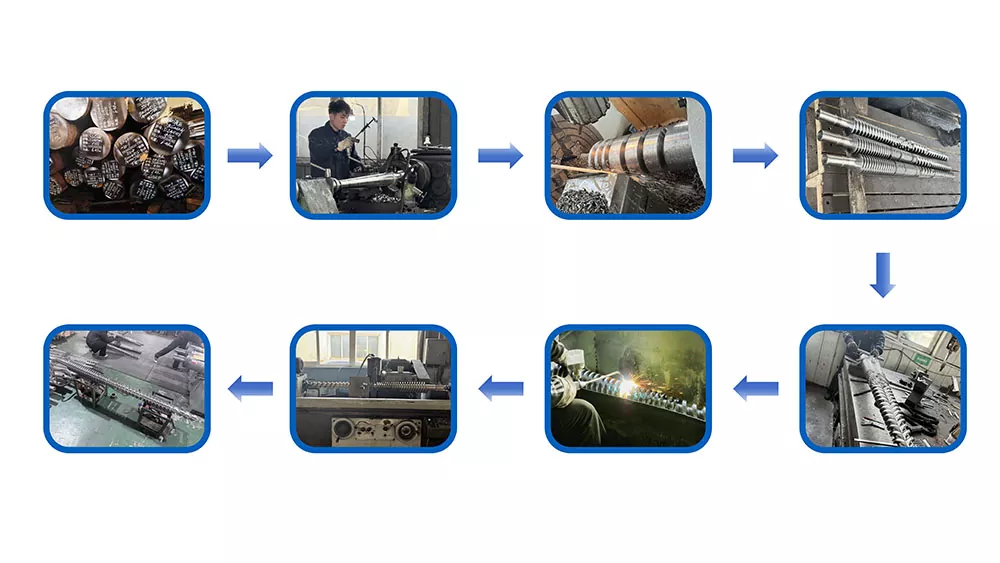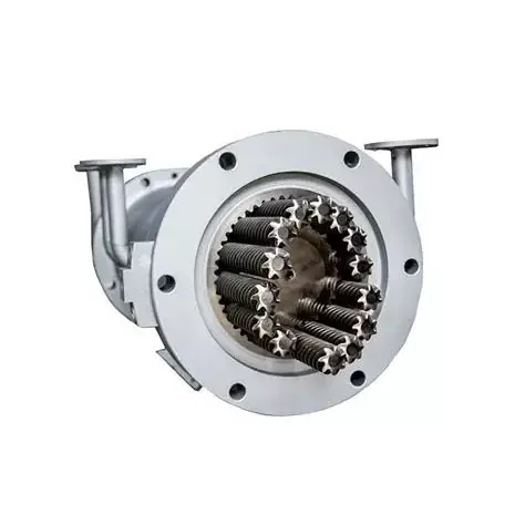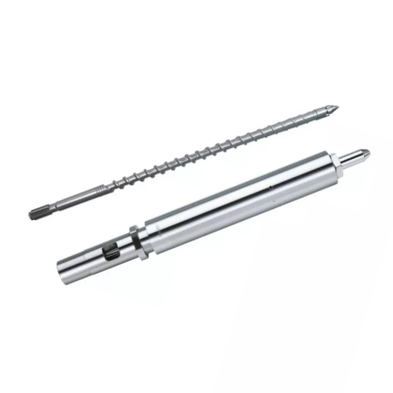

Abrasive feedstock does not need the hardest catalog number. It needs the right geometry, protected wear zones, compatible barrel and measurable acceptance plan. This guide explains how we turn material and production data into a screw specification that a buyer can inspect.
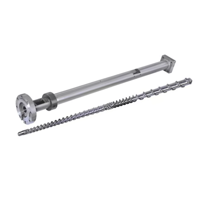
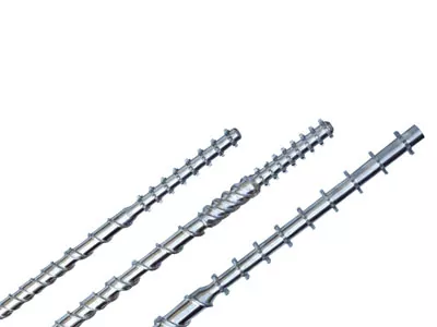
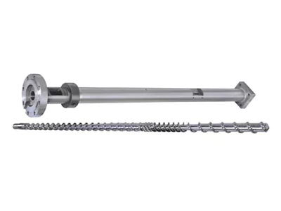
Quick answer
To specify a wear-resistant single screw, send the exact resin and grade, filler or fiber type and percentage, recycled content, contamination, feed form, moisture, MFR or MVR test condition, required output, screw speed, motor load, melt pressure, temperature, operating hours and the present wear map.
Then select the surface by damage location. Nanhaiya offers 38CrMoAlA, SACM645, 42CrMo and forged-steel substrates, with deep ion nitriding, PTA protection on flight tops and sides, plus tungsten carbide and nickel-based surface options. The proposed screw must be checked with the mating barrel, because a new hard surface cannot correct an enlarged or misaligned bore.
When a normal single screw specification is no longer enough
Glass fiber, carbon fiber, calcium carbonate, talc and hard contamination can remove metal from the screw and barrel. Corrosive additives or degradation products can pit the working surface. Recycled feed may add moisture, dirt, mixed polymers and an unstable bulk form to the same machine.
The buying trigger is not simply that the formulation contains filler. It is a repeatable production or condition problem: flight diameter loss, rounded edges, a washed-out barrel zone, falling output at the same rpm, rising motor load, unstable pressure, contamination from metal or a service interval that no longer fits the plant.
| Evidence from the line | What we check at the factory | What the purchase decision may change |
|---|---|---|
| Uniform flight-tip loss through a high-pressure zone | Filler, screw speed, pressure, alloy coverage and mating barrel bore | Targeted PTA protection, wider alloy coverage or a matched barrel |
| Deep score at one angular position | Foreign material, straightness, alignment, bearings and barrel ovality | Correct the mechanical cause before copying the damaged screw |
| Pitting or layer loss | Resin, additives, moisture, cleaning chemistry and temperature history | Select for corrosion and bond integrity, not hardness alone |
| Output falls while rpm stays constant | Screw OD, barrel ID, leakage clearance, melt condition and downstream pressure | Measure the pair before deciding on screw-only replacement |
| Short life after every replacement | Whether the same material, geometry and damage mechanism were repeated | Redesign the wear system instead of buying another direct copy |
Our factory view: if an RFQ says only "90 mm screw for recycled PP," it is not ready for a flight drawing. We want to know what enters the hopper, where the old part lost metal and what the line was doing when performance changed. A hard alloy without that evidence is still a guess.
If the old component is already available, use our single screw and barrel wear measurement guide. It maps screw outside diameter and barrel inside diameter by axial station instead of reducing the whole condition to one number.
What Nanhaiya publishes for its super wear-resistant single screw
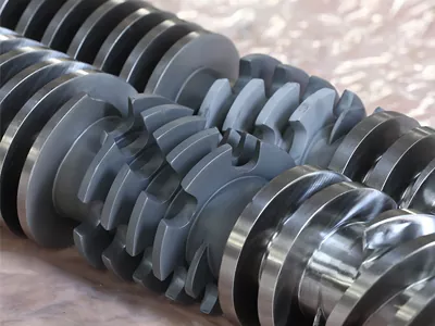
Our super wear-resistant single screw is made for demanding formulations that include glass-fiber-reinforced plastics, calcium carbonate, talc, high-performance recycled material, recycled waste and corrosive plastics. The current material examples include GFPA, GFPBT, GFPPS, GFPP, GFPOM, carbon-fiber compounds and PPS.
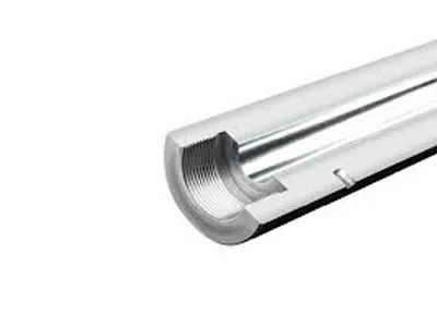
The range starts with a strong core and adds a duty-specific surface. Listed substrate options include 38CrMoAlA, SACM645, 42CrMo and high-density forged steel. Our matching alloy barrel uses a carbon-steel body with a centrifugally cast or applied wear-resistant bore layer whose hardness exceeds HRC 60.
| Published field | Nanhaiya product range | How to use it in an RFQ |
|---|---|---|
| Common screw diameters | 35, 45, 65, 75, 85 and 90 mm | Select the machine fit first, then approve finished OD and barrel ID by station |
| L/D | 20:1 to 30:1 | Match available barrel length, melting, residence time, venting and pressure duty |
| Compression ratio | 3.5:1 to 4.5:1 | Confirm the exact definition and geometry for the processed compound |
| Heating and cooling zones | Usually 5 to 6, depending on diameter and equipment | Send the existing barrel-zone drawing and control arrangement |
| 65 mm pipe example | 25 to 35 rpm for 3 mm wall pipe; 45 to 90 kW drive | Treat as one published application example, not a universal filled-material setpoint |
| Published temperature example | Feed 160 to 170 C; melting 180 to 190 C; die 175 to 185 C | Use the material supplier and approved process window for the actual recipe |
| Ion nitriding | Published surface hardness up to HV 1000 to 1200 | State the test method, load, location and acceptance range for the order |
| Protected areas | PTA on the flight top and side surfaces | Mark the axial coverage and finished alloy area on the drawing |
| Coating options | Tungsten carbide and nickel-based alloys | Identify the exact alloy, process, thickness basis and compatible barrel |
For the sprayed or coated configurations in this range, our published data states that service life can increase by three to eight times. That improvement belongs to the selected high-wear condition. The quotation should define the processed material, former screw baseline, protected area and operating duty if service life becomes a contract requirement.
Useful limit: the figures above describe our available product range. They are not permission to combine the largest compression ratio, hardest surface, highest speed and every alloy into one screw. The finished order is one controlled configuration.
Define the feedstock as a range, not a trade name
Filled and recycled materials often arrive under a short commercial description. That is not enough for screw selection. Two GFPA compounds can use different fiber levels, resin viscosity, additives and moisture limits. Two recycled PP streams can differ in contamination, ash, MFR, particle form and bulk density.
Write the normal recipe and the worst recipe separately. A screw that works with clean 15 percent mineral-filled pellets may not survive the same output target when the line changes to 40 percent filler, irregular regrind and abrasive contamination.
Ash or filler content
ISO 3451-1:2026 provides general methods for determining ash in plastics. Use the relevant material-specific part where applicable, then report the test method with the result.
Water content
ISO 15512:2019 covers water-content methods for powders, granules and finished plastic articles. Moisture belongs in the feed specification, especially for hygroscopic resins and washed recycled feed.
MFR or MVR
ISO 1133-1:2022 measures MFR and MVR at specified temperature and load. The standard notes that MVR is useful when comparing different filler contents and filled with unfilled thermoplastics.
| Material field | What to report | Why the screw factory needs it |
|---|---|---|
| Polymer | Maker, grade, blend ratio and approved substitutes | Sets the melting, viscosity, temperature and corrosion context |
| Fiber | Glass or carbon, weight percent, initial length and pellet form if known | Changes abrasion, feeding, breakage sensitivity and property target |
| Mineral | Calcium carbonate, talc or other mineral, weight percent and particle data | Changes abrasion, bulk behavior, heat demand and melt rheology |
| Recycled fraction | Percentage, source, washing, sorting and batch variability | Identifies the likely contamination and operating window |
| Feed form | Pellet, powder, flake, regrind, agglomerate or mixed stream | Controls feed-section grip, channel filling and output stability |
| Moisture | Result, method, drying process and storage condition | Affects melting, venting, degradation and corrosion risk |
| MFR or MVR | Value, temperature, load, preparation and sampling date | Provides a controlled flow reference, not a complete process model |
| Contamination | Metal, sand, glass, paper, wood and incompatible polymer evidence | Separates normal compound abrasion from preventable foreign material damage |
What we ask first: send a current technical data sheet and a representative sample, but do not stop there. The sample may show only the best batch. We also want the production range, the rejected material and the contamination that appears after washing, grinding and storage.
For pelletizing work, our granulation single screw guide adds feed form, venting, filtration and pelletizer data. The granulation screw and barrel product is the relevant product path when the duty includes recycling, masterbatch or plastics modification.
Separate abrasion, corrosion, adhesion and metal contact
A surface can lose material for more than one reason. Hard particles cut and polish the flight. Corrosive chemistry creates pits and weakens the surface. Polymer deposits can hold degraded material. Misalignment or an enlarged barrel can permit metal contact. A single hardness value cannot distinguish these mechanisms.
| Observed pattern | Likely review branch | Evidence to collect |
|---|---|---|
| Smooth rounded flight edges in the same axial zone | Abrasive wear under pressure | Filler type and level, rpm, output, pressure and wear-station map |
| Sharp grooves with embedded particles | Hard foreign material | Magnet, screen and sorting records; residue sample and particle analysis |
| Fine pits or rough chemical attack | Corrosion or degradation products | Resin, additives, moisture, temperature, shutdown and cleaning history |
| Smearing, raised metal or matching screw and barrel scars | Mechanical contact | Straightness, bore ovality, alignment, bearing and thrust condition |
| Layer chip or local peel | Bond, impact, edge preparation or repair history | Process record, cross-section if specified, cleaned photos and layer location |
| Black residue without confirmed metal loss | Stagnation, degradation or cleaning issue | Material sequence, purge result, screen, adapter, die and clean-surface inspection |
Our article on premature single screw surface wear follows these cause branches. If the surface is still covered by polymer, use the single screw cleaning guide before deciding that every dark area is missing metal.
Do not diagnose metal contact as a material problem. A more wear-resistant flight can still score a barrel if the screw is bent, the bore is oval, the thrust system is damaged or installation alignment is wrong. Correct the mechanical cause before installing the replacement.
Protect the location that actually wears
The screw does not see one uniform duty from hopper to discharge. The feed zone handles solids and can receive hard contamination. The compression or melting region combines solids, rising pressure and heat. The metering section carries a pressurized melt. Mixing features add edges, flow division and local shear.
Nanhaiya uses PTA welding on the top and side surfaces of the flights because these are common high-wear locations. The correct axial length still depends on the measured damage and the new formulation. Protecting the first 400 mm means little if the existing wear peak sits farther downstream.
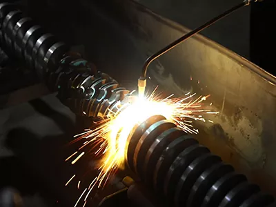
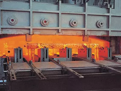
- Mark the old screw by station. Use the same physical datum for every measurement and photograph.
- Record the mechanism beside the number. Note polish, groove, pit, chip, raised metal or deposit at each station.
- Map the barrel at matching depths. Record maximum and minimum bore readings in more than one angular direction.
- Overlay the process. Add feed opening, compression, vent, mixing section, screen changer and pressure measurement locations.
- Draw the protected area. State flight top, flank, root or broader coverage, including the axial start and stop.
Our factory view: we prefer a short wear map with reliable locations over twenty photographs with no orientation. Once the damage zone is tied to the screw drawing, alloy can be placed where it earns its cost instead of making the whole part harder by default.
Choose a complete surface system, not one impressive hardness number
Ion nitriding, PTA hardfacing, tungsten carbide and nickel-based systems are different constructions. They change the protected location, metallurgy, finishing method, inspection and relationship with the barrel. The selection begins with the damage mechanism and ends with the finished screw and barrel pair.
| Surface route | Where it can fit | What the order must define |
|---|---|---|
| Deep ion nitriding | A treated-steel surface for a verified wear and dimensional duty | Base material, process, hardness method, test location, case requirement and final dimensions |
| PTA flight hardfacing | Targeted protection on flight tops and sides in known high-wear zones | Alloy, coverage, deposit basis, bond or process evidence, finishing and barrel compatibility |
| Tungsten carbide surface | Severe abrasive duty when the complete material pair and manufacturing route are approved | Composition, process, coverage, thickness basis, finish, toughness and counterface approval |
| Nickel-based alloy | Wear and corrosion duties suited to the selected alloy chemistry | Exact alloy, application method, protected area, hardness method and corrosion context |
| Bimetallic barrel lining | A compatible wear-resistant bore around the new or rebuilt screw | Lining material, thickness basis, hardness method, bore geometry, finish and final clearance |
Nanhaiya publishes ion-nitrided hardness in Vickers units and alloy-barrel hardness in Rockwell C units. These are different test systems. ISO 6507-1:2023 specifies Vickers testing for metallic materials and coatings within its scope. ISO 6508-1:2023 specifies Rockwell and superficial Rockwell methods.
Do not compare HV and HRC as if they were one direct purchasing scale. State the method, force or scale, test surface, sampling location and acceptable range. Also record layer depth, alloy coverage, substrate, bond or process evidence and final geometry where the selected construction requires them.
Our opinion: a hard layer on the wrong flight diameter is a rejected screw, not a premium screw. Hardness supports the design. It never replaces geometry, layer integrity, straightness or compatibility with the barrel.
For a direct treatment comparison, read nitrided versus bimetallic single screws. This article owns the application and buying process. The comparison article owns the differences between surface constructions.
Get the geometry right before upgrading the surface
Filled material changes more than wear. It can change feeding, melting, shear heating, pressure demand and mixing. Copying the outside dimensions of the old screw may preserve a geometry that was designed for clean resin or a lower filler level.
At the same time, more compression or more mixing is not automatically better. An aggressive section can add motor load, melt temperature and pressure. A protected surface will survive longer only if the geometry works inside a stable process window.
| Geometry field | Question to answer | Evidence to send |
|---|---|---|
| Feed section | Can the actual pellet, powder, flake or regrind enter and fill consistently? | Feed form, bulk density range, hopper and throat drawing, force feeder if used |
| Compression transition | Where should solids compact and melt without excessive heat or load? | Resin, filler, output, temperature, motor load and present melting symptoms |
| Metering section | What pressure and output must the screw deliver against the downstream system? | Screen, breaker plate, die, clean and dirty pressure, product dimensions |
| Mixing feature | Is the problem distribution, agglomerate breakup, temperature uniformity or none? | Product defect, compound data, samples and current screw performance |
| Venting | What volatile or moisture load must leave, and where can pressure be rebuilt? | Drying, moisture, vacuum, vent position, barrel length and flooding history |
| Mechanical interfaces | Will the screw fit the gearbox, thrust arrangement, seal, barrel and downstream adapter? | Approved dimensioned drawings and fresh mating-part measurements |
Nanhaiya's single screw range covers pipe, sheet, film, profile and granulation duties. That application spread is why diameter alone cannot select the internal geometry. A 65 mm pipe screw and a 65 mm recycled granulation screw may share an outside diameter while doing different process work.
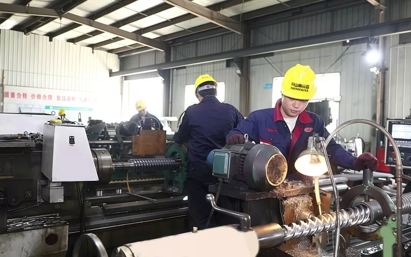
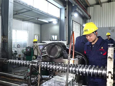
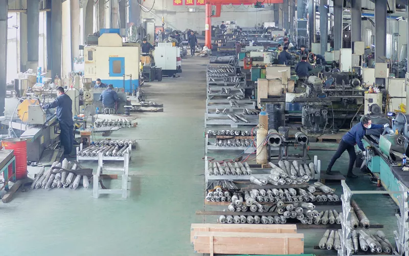
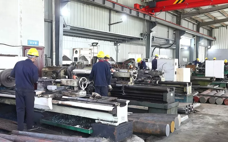
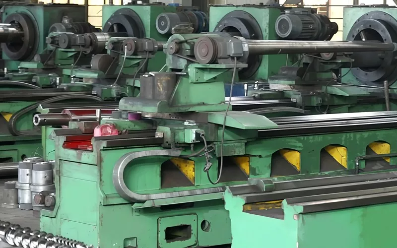
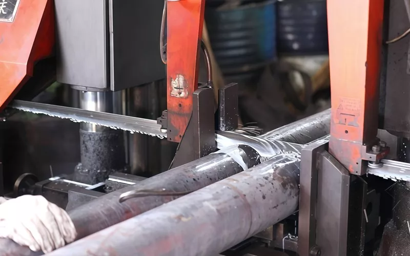
Our factory uses CNC saws with published feed error at or below 0.1 mm, long-workpiece CNC lathes, drilling and milling equipment with 0.02 mm positioning accuracy, and five-axis machining for complex structures. Those capabilities support the drawing. They do not remove the need to define the drawing correctly.
Approve the screw and barrel as one working pair
A new screw runs inside the actual barrel, not inside the nominal bore on an old catalog. If that bore is enlarged, oval, tapered, scored or misaligned, the new part may still leak melt over the flight or contact the counterface.
Measure barrel ID and screw OD at corresponding axial stations. Record maximum and minimum readings, not only averages. Define whether the order uses diametral clearance or radial clearance. If the old barrel remains in service, the factory needs its present geometry before setting the finished screw diameter.
| Barrel condition | Usual review direction | Why |
|---|---|---|
| Bore remains round, measured and suitable | Review screw-only replacement against the confirmed bore map | The new screw can be sized to a known counterface |
| Bore is enlarged or oval in the main pumping zone | Review a matched screw and barrel replacement | A new screw alone may retain excessive or uneven clearance |
| Both parts show matching score or metal transfer | Find alignment, bearing, thrust or foreign-material cause first | The same mechanical fault can damage the replacement |
| Old barrel surface is unknown | Identify construction and obtain compatibility approval | The new hardfacing and old counterface may be an unsuitable pair |
| Production duty has changed | Treat the project as a redesign, not a copy | Old geometry and surface coverage may not match the new formulation |
Our factory position: a screw-only quote is a part price. It becomes a technical recommendation only after the barrel condition and running pair are understood. We would rather ask for bore data now than explain poor output after a perfect-looking screw is installed.
Use the decision framework in replace the screw only or both screw and barrel before finalizing scope.
Wear-resistant single screw RFQ checklist
A complete RFQ lets the factory separate machine fit, process performance and surface life. Mark unknown information as unknown. Do not invent an old dimension or material grade to complete the form.
- Machine maker, model and serial reference
- Extrusion, granulation or injection application
- Resin maker, grade and blend ratio
- Glass or carbon fiber type and weight percent
- Calcium carbonate, talc and other filler levels
- Recycled percentage and source range
- Feed form, particle size and bulk density
- Moisture result, method and drying process
- MFR or MVR value, temperature and load
- Contaminants and sorting or filtration method
- Normal and maximum saleable output
- Screw speed range and gearbox ratio
- Motor power and load trend
- Barrel-zone and melt-temperature records
- Melt pressure and downstream restriction
- Hours per day and starts per shift
- Existing screw drawing and connection data
- Barrel drawing, heaters, ports and interfaces
- Screw OD and barrel ID map by station
- Cleaned-surface photos with orientation
- Known substrate, coating and repair history
- Current defect and production loss
- Required surface and dimensional reports
- Packaging, quantity and delivery destination
For a replacement order, combine this checklist with the replacement single screw specification guide. It covers the mechanical connection, overall length, datum structure and sample-copy risks in greater detail.
Turn the specification into an inspection plan
An acceptance plan should tell both parties what will be measured, where it will be measured and which record will be supplied. The inspection must follow the finished screw, not stop after the substrate or treatment stage.
| Acceptance item | What to define before production | Useful record |
|---|---|---|
| Identity and traceability | Order, drawing revision, component ID and material designation | Traveler, marking and material record |
| Surface coverage | Axial start and stop, flight top, sides, root or broader area | Approved drawing and process record |
| Hardness | Method, scale or force, location, quantity and accepted range | Order-specific hardness report |
| Layer or deposit | Depth or thickness basis, sampling route and bond evidence when required | Cross-section, coupon or qualified process evidence as agreed |
| Flight outside diameter | Stations, angular directions, temperature and tolerance | Finished OD map |
| Barrel inside diameter | Corresponding depths, angular directions and tolerance | Finished or existing-bore map |
| Clearance | Radial or diametral definition at each controlled zone | Matched-pair calculation sheet |
| Straightness and runout | Datums, support method, measurement positions and limits | Final inspection report |
| Geometry | Pitch, channel depths, transition, mixer, tip and connection | Dimension report against the approved drawing |
| Surface condition | Finish requirement and visual rejection conditions by zone | Inspection record and close-up photographs |
Keep hardness scales separate. HV 1000 to 1200 on a nitrided surface and HRC above 60 on an alloy barrel are not two versions of the same test. The purchase order should identify the applicable method and location for each surface.
Build a baseline on the first stable production run
A replacement is not fully evaluated when it rotates without contact. Run the approved formulation to a stable condition and save a baseline for output, rpm, motor load, melt pressure, melt temperature and product quality. Record the die, screen pack, feeder and material lot.
Compare future data at similar material and operating conditions. If output falls while rpm rises, or if motor load, pressure and temperature move together, diagnose the whole process before increasing speed. Our screw speed, melt temperature and output guide explains why one setting changes the others.
| Baseline field | Record at start-up | Use during service |
|---|---|---|
| Material | Grade, recipe, filler, recycled fraction, moisture and lot | Separate hardware change from feedstock change |
| Production | Saleable kg/h, rpm and feeder setting | Track conveying and pumping performance |
| Drive | Motor current or load at stable output | Identify rising mechanical or process demand |
| Thermal | Barrel settings and measured melt temperature | Detect added shear heat or poor melting |
| Pressure | Stable melt pressure with the stated filter and die | Separate screw behavior from downstream restriction |
| Quality | Dimensions, appearance, color and required material tests | Connect process changes to saleable product |
| Condition | New-part OD, barrel ID, photos and surface record | Measure wear as change from a real baseline |
What we would not do: install a new screw, run a different recipe and call the output difference a screw result. Hold the comparison conditions as steady as production allows. If the recipe changes, record it and start a new reference line.
Frequently asked questions
What information is needed to quote a wear-resistant single screw?
Send the resin maker and grade, filler or fiber type and weight percentage, recycled percentage, contamination, moisture, MFR or MVR with test condition, feed form, target output, screw speed, motor load, melt pressure, temperature profile, operating hours, machine and barrel drawings, measured screw and barrel wear map, current surface system and required inspection documents.
Is a nitrided screw enough for glass-filled plastic?
It can be suitable for some verified duties, but the words glass-filled do not decide the surface. Fiber percentage, resin, throughput, speed, wear location, barrel counterface and required life all matter. Severe localized abrasion may justify PTA hardfacing or another alloy system on the flight top and sides, paired with a compatible barrel.
Which materials and wear treatments does Nanhaiya offer for this single screw?
Nanhaiya lists 38CrMoAlA, SACM645, 42CrMo and high-density forged steel as substrate options. Published surface routes include deep ion nitriding, PTA deposition on flight tops and sides, and sprayed or coated tungsten carbide and nickel-based alloys. The final combination is selected for the actual compound and wear map.
Can I install a wear-resistant screw in an old nitrided barrel?
Do not approve that pairing from material names alone. Measure the old barrel bore by axial station and angular direction, confirm its lining or surface, and obtain compatibility approval for the proposed screw surface. An enlarged, oval or badly scored barrel can leave excessive clearance or damage the new screw.
What dimensions does Nanhaiya publish for super wear-resistant single screws?
Nanhaiya lists common diameters of 35, 45, 65, 75, 85 and 90 mm, with L/D commonly from 20:1 to 30:1 and compression ratio commonly from 3.5:1 to 4.5:1. These are product-range references. The order drawing must define the exact geometry, interfaces, treatment and mating barrel.
How should filler and recycled content be reported in an RFQ?
State each ingredient by material type and weight percentage, including glass or carbon fiber, calcium carbonate, talc, pigment, flame retardant and recycled fraction. Add particle or fiber information when available, plus ash test method, moisture method, MFR or MVR condition, feed form and the normal and worst production recipes.
How should a hardfaced single screw be inspected before shipment?
Approve the drawing and inspection plan first. Check identity and traceability, base material, protected locations, treatment record, applicable hardness method and test locations, finished flight diameter by station, straightness, pitch and channel geometry, connection dimensions, surface condition and the matching barrel bore and clearance definition.
What should be monitored after the new screw is installed?
Save a clean baseline for output, screw speed, motor load, melt pressure, melt temperature, product quality and wear measurements. Trend the same values at comparable material and operating conditions. Investigate a changing pattern before increasing speed or temperature, and record axial wear locations at planned shutdowns.
Sources checked
Nanhaiya first-party pages: Super Wear-Resistant Single Screw; Single Screw; Granulation Single Screw Barrel; Production Equipment; Our Service; Company Profile.
Official technical references: ISO 3451-1:2026, Plastics, determination of ash; ISO 15512:2019, Plastics, determination of water content; ISO 1133-1:2022, MFR and MVR of thermoplastics; ISO 6507-1:2023, Vickers hardness test; ISO 6508-1:2023, Rockwell hardness test.
Editorial note: Product data, company capabilities and photographs come from Nanhaiya's official website and are written as Nanhaiya first-party information. ISO references support the named test methods. Final geometry, materials, treatment, tolerances, life commitment, inspection and commercial terms are controlled by the approved drawing, quotation and purchase contract.