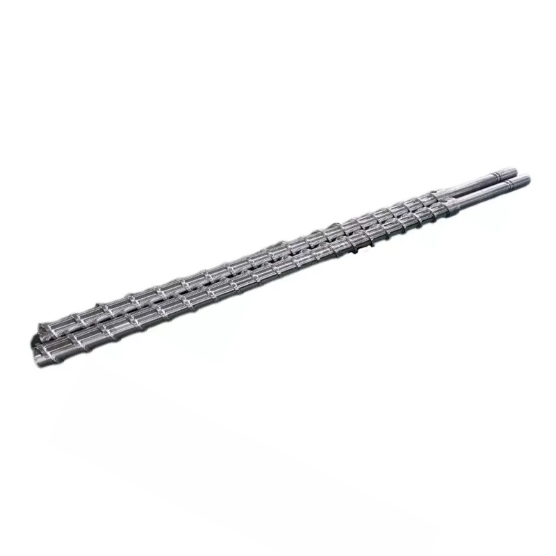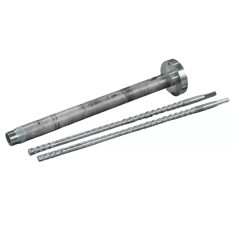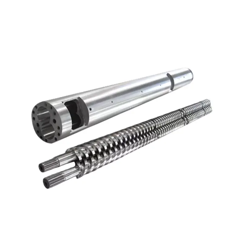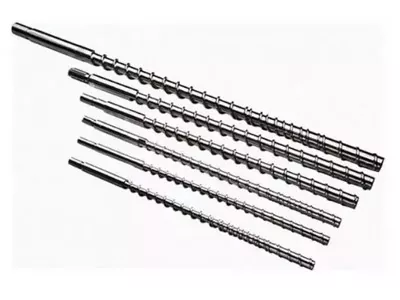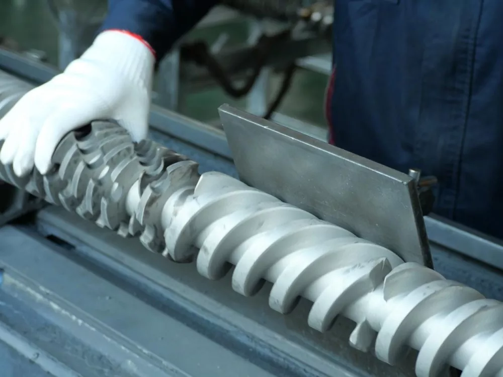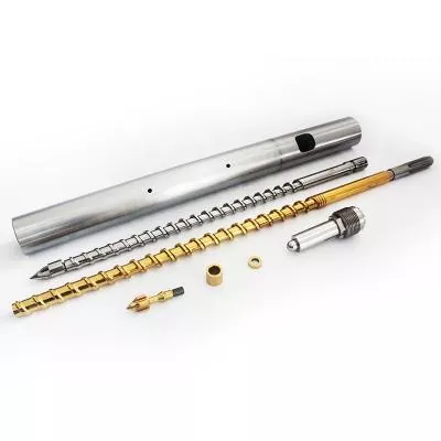

High speed is not a motor label or one impressive rpm. It is a stable operating window in which the screw, barrel, gearbox, heaters, cooling system and die produce saleable PE or PP at controlled temperature and load. This guide shows what a buyer should define before a drawing, price or output promise is approved.
Quick answer
Specify a PE or PP high-speed single screw by the real material, saleable output, product and die, screw surface speed, melt-temperature window, pressure, motor and gearbox duty, cooling capacity, wear environment and acceptance method. Do not buy from diameter and maximum rpm alone.
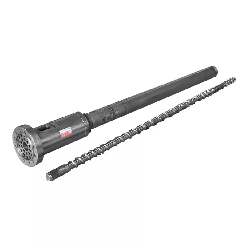
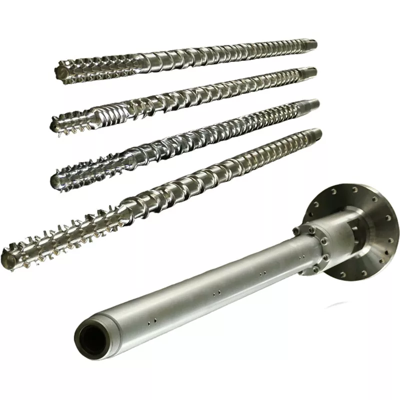
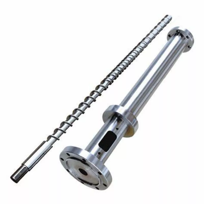
Nanhaiya publishes nine single-screw models from NHY20 to NHY150, with output ranges from 3 to 1,300 kg/h and speed ranges from 10 to 150 rpm across the family. Its PE and PP high-speed product uses optimized screw geometry, a high-torque gearbox, special feed-slot barrels and wear-resistant alloy construction. Turn every project target into a stable test point using the named resin, die, quality window and electrical measurement boundary.
High speed is a system specification, not an rpm
When a buyer asks me for a 150 rpm screw, my next question is diameter. A 45 mm screw at 150 rpm and a 75 mm screw at 150 rpm do not have the same surface speed, channel volume, melting duty or torque requirement. The product, die and downstream cooling system can also become the limit before the drive reaches its maximum speed.
A useful high-speed specification connects six things: what enters the hopper, what the screw does to it, what the gearbox can deliver continuously, what the barrel can heat and cool, what the die resists, and what the finished product must pass. If one is missing, the maximum rpm is only a mechanical number.
| Buyer phrase | What it does not define | Better purchasing language |
|---|---|---|
| High-speed PE screw | PE grade, diameter, surface speed, product or quality window | State the exact resin, screw diameter, stable rpm range, output and melt limits |
| High-output PP line | Whether output means gross material or saleable product | State saleable kg/h at agreed dimensions, defects, pressure and temperature |
| Energy-saving design | The electrical boundary, baseline and quality condition | Compare measured kWh/kg at the same resin, die and accepted product quality |
| Wear-resistant screw | Alloy, coverage, depth, test method and barrel counterface | Put the surface construction and inspection locations on the drawing |
| Fits our existing extruder | Connection, thrust, feed opening, bore condition and alignment | Approve a dimensioned interface drawing and current barrel measurements |
Our factory view: I would rather receive five stable operating points than one heroic maximum. A line that reaches top rpm for five minutes but drifts in pressure, overheats the melt or makes off-size pipe has not passed a high-speed test.
If the immediate question is how rpm changes temperature and output during operation, use our separate guide to screw speed, melt temperature and output. This page focuses on buying and acceptance.
Nanhaiya's published single-screw model range
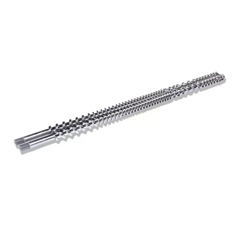
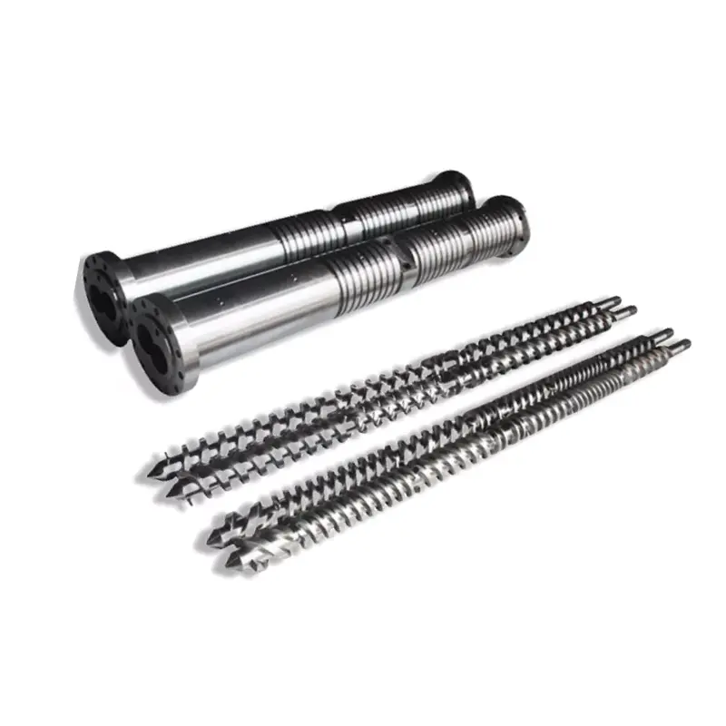
The Nanhaiya PE and PP high-speed single screw is offered for pipe extrusion and other continuous PE and PP duties. Our current page pairs optimized screw structure with high-torque gearboxes and special feed-slot barrels. It also lists a twofold efficiency improvement compared with traditional equipment and a design that can reduce PP extrusion temperature and energy use.
For procurement, those advantages should become a testable project definition. Fix the comparison machine, resin lot, product, die, filter condition, quality window, stabilization time and electrical boundary. That is how a useful factory statement becomes an acceptance result.
| Model | L/D | Published output | Published speed | Driving motor | Center height |
|---|---|---|---|---|---|
| NHY20 | 20:1 | 3 to 5 kg/h | 10 to 60 rpm | 1.1 / 1.5 / 2.2 kW | 1,000 to 1,400 mm |
| NHYZS25 | 25:1 | 5 to 8 kg/h | 10 to 60 rpm | 2.2 / 3.0 / 4.0 kW | 1,000 to 1,400 mm |
| NHY30 | 25:1 | 5 to 10 kg/h | 10 to 60 rpm | 2.2 / 3.0 / 4.0 kW | 1,000 to 1,400 mm |
| NHY45 | 25:1 to 36:1 | 10 to 120 kg/h | 10 to 150 rpm | 5.5 to 22 kW | 1,000 to 1,400 mm |
| NHY65 | 25:1 to 36:1 | 60 to 300 kg/h | 20 to 150 rpm | 22 to 75 kW | 1,000 mm |
| NHY75 | 25:1 to 36:1 | 200 to 450 kg/h | 20 to 150 rpm | 30 to 132 kW | 1,000 mm |
| NHY90 | 25:1 to 36:1 | 180 to 600 kg/h | 20 to 110 rpm | 30 to 185 kW | 1,000 to 1,100 mm |
| NHY120 | 25:1 to 36:1 | 320 to 1,000 kg/h | 20 to 90 rpm | 75 to 280 kW | 1,000 to 1,250 mm |
| NHY150 | 25:1 to 36:1 | 400 to 1,300 kg/h | 20 to 75 rpm | 90 to 400 kW | 1,000 to 1,300 mm |
These are published family ranges, not nine fixed machine packages. Do not combine the highest output, speed, motor and L/D in one row and assume that combination is automatically available for every resin and die.
Define the PE or PP feedstock before selecting the screw
PE and PP are families, not complete screw specifications. HDPE pressure-pipe compound, recycled HDPE flake, LDPE film resin and mineral-filled PP can enter the same conversation while demanding different feeding, melting, mixing and wear decisions.
ISO 17855-1 identifies polyethylene moulding and extrusion materials through a designation system that includes material form and additives. ISO 19069-1 does the same for polypropylene and includes information such as MFR, application, processing method, additives, fillers and reinforcing materials. Use the resin maker's current technical data with that material identity.
MFR or MVR
Report the value with its test temperature and load. ISO 1133-1 notes that these quality-control methods use lower shear rates than normal processing, so one MFR number cannot predict a high-speed extrusion window.
Water content
Report the test method, result, drying and storage. ISO 15512 covers water-content methods for PE, PP, powders, granules and finished plastic articles.
Processing rheology
ISO 11443 covers capillary and slit-die rheometry at processing-relevant shear rates. Use actual rheology data when a difficult material needs more than an MFR reference.
| Material field | What to send | Why it changes the screw decision |
|---|---|---|
| Polymer identity | PE or PP family, maker, grade and allowed substitute grades | Sets the melting, viscosity and temperature context |
| Feed form | Pellet, powder, flake, regrind, agglomerate or blend | Changes feed-channel filling, grip and output stability |
| Flow reference | MFR or MVR value, temperature, load and sample preparation | Allows controlled grade comparison but not full process prediction |
| Recycled content | Percentage, source, sorting, washing and batch variation | May add variable bulk density, moisture and contamination |
| Filler and pigment | Type, weight percentage and particle or fiber data | Changes wear, energy input, mixing and finished properties |
| Additives | Stabilizer, slip, carbon black, masterbatch and other recipe items | May change dispersion, friction, corrosion and temperature sensitivity |
| Moisture and volatiles | Method, result, drying and venting requirement | Changes surface quality, pressure stability and degradation risk |
| Product standard | Pipe, film or other product specification and test plan | Defines the quality window the screw must support |
What I want to see in the RFQ: list the normal material and the most difficult approved material. Designing around the best-flowing virgin grade while the plant regularly runs recycled blend or filled PP creates a drawing that is precise but wrong.
For recycled pelletizing duties, use the more detailed single screw design guide for granulation. For film applications, the LDPE and HDPE film single screw adds diameter and L/D choices for the formulation and film line.
Convert rpm into screw surface speed
Rpm tells us how often the screw turns. Surface speed tells us how fast the flight surface moves relative to the barrel. That makes it a better first comparison when diameters differ.
Screw surface speed: v = π × D × N / 60
Use D in metres, N in revolutions per minute and v in metres per second.
| Published model point | Diameter used in calculation | Speed | Calculated surface speed | What the comparison shows |
|---|---|---|---|---|
| NHY45 upper speed | 45 mm | 150 rpm | About 0.35 m/s | High rpm on a smaller diameter does not mean the highest surface speed |
| NHY65 upper speed | 65 mm | 150 rpm | About 0.51 m/s | The same rpm moves a larger flight surface faster |
| NHY90 upper speed | 90 mm | 110 rpm | About 0.52 m/s | Lower rpm can produce almost the same surface speed on a larger screw |
| NHY150 upper speed | 150 mm | 75 rpm | About 0.59 m/s | The largest published model reaches the highest value in this simple comparison |
The calculation uses nominal model diameter and the upper published rpm only to explain the relationship. It is not an approved operating point or output guarantee.
Surface speed still does not describe channel depth, pitch, barrier geometry, feed filling, resin viscosity or die resistance. Use it to ask a better question, not to choose the screw by one number.
Practical decision: compare different diameters by surface speed, then compare the actual line by stable output, melt quality, pressure, load and specific energy. This prevents a smaller high-rpm screw and a larger lower-rpm screw from being judged by rpm alone.
Specify saleable output, specific output and energy
Output belongs to a condition. State the resin, product, die, wall thickness, screen condition, speed, melt temperature, pressure and quality limits beside every kg/h value. Gross material through the hopper is not the same as saleable product after start-up scrap and dimensional rejection.
Specific output: q = Q / N, where Q is kg/h and N is rpm.
Specific energy: SEC = P / Q, where measured electrical power P is kW and saleable output Q is kg/h. The result is kWh/kg.
Specific output helps show whether each additional revolution still moves proportional material. Specific energy helps compare electrical demand, but only when both tests use the same measurement boundary. A drive-only reading cannot be fairly compared with a whole-line reading that includes heaters, cooling, vacuum and downstream equipment.
| Trend as rpm increases | Possible interpretation | Next evidence to collect |
|---|---|---|
| Saleable output rises and q remains stable | Feeding and pumping may still be inside a useful range | Confirm melt variation, pressure, load and product dimensions |
| Gross output rises but scrap also rises | The line is moving more material without creating more accepted product | Separate gross, saleable and rejected kg/h |
| Rpm rises while q falls | Feed filling, melting or downstream restriction may be limiting | Check bulk feed, melt condition, screen and die pressure |
| SEC rises sharply | Resistance, heat generation or an inefficient operating point may be increasing | Verify the power boundary, filter condition, pressure and cooling response |
| Output is stable but dimensions drift | The die, cooling or haul-off may be outside its control window | Trend product dimensions with line speed, cooling and melt pressure |
Do not approve output from one peak reading. Require a defined stabilization period and an agreed sampling interval. Record both average and variation. A good purchasing test makes unstable performance visible instead of averaging it away.
Match screw geometry to feeding, melting and die resistance
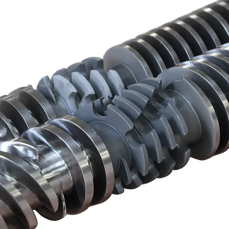
High-speed geometry must finish melting within a shorter residence time without creating an unacceptable melt-temperature rise. That can involve the feed section, compression profile, barrier or mixing features, metering capacity and the barrel feed slot. The right answer depends on the actual PE or PP grade and product.
Nanhaiya's current product page combines a full-alloy wear-resistant screw with a special feed-slot barrel for stable melt extrusion in thin-wall and thick-wall pipe. It also uses optimized screw structure with a high-torque gearbox. These are related choices: the feed system must fill the screw, the screw must melt and pump, and the drive must support the required torque through the full window.
| Design area | Question the buyer should answer | Evidence for the screw factory |
|---|---|---|
| Feed section | Will pellets, powder or recycled feed enter and fill consistently at the target rate? | Feed form, bulk-density range, hopper, throat and feeder details |
| Compression and melting | Can solids melt within the available length and residence time? | Resin, MFR or rheology, temperature, present unmelts and load trend |
| Barrier or mixing feature | Is the need solids separation, distributive mixing, color dispersion or temperature uniformity? | Defect samples, quality target and current screw drawing |
| Metering section | What stable pressure and flow must be delivered against the die? | Clean and dirty pressure, screen pack, breaker plate, adapter and die data |
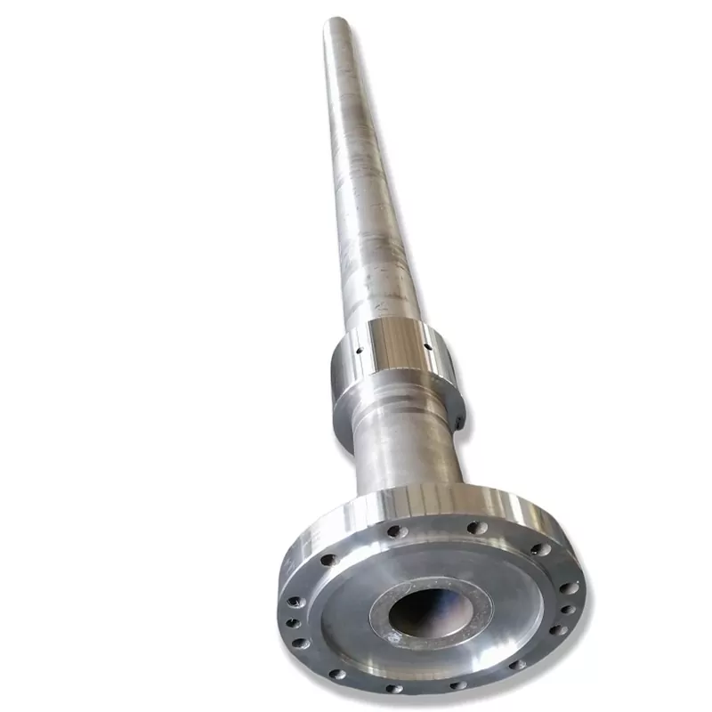
| Feed-slot barrel | How will the barrel support solids conveying without unstable overfeeding? | Throat temperature, cooling, groove or slot details and feed behavior |
| Mechanical interfaces | Will the part fit the gearbox, thrust system, barrel and downstream connection? | Approved dimensioned drawings and fresh measurements |
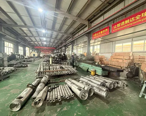
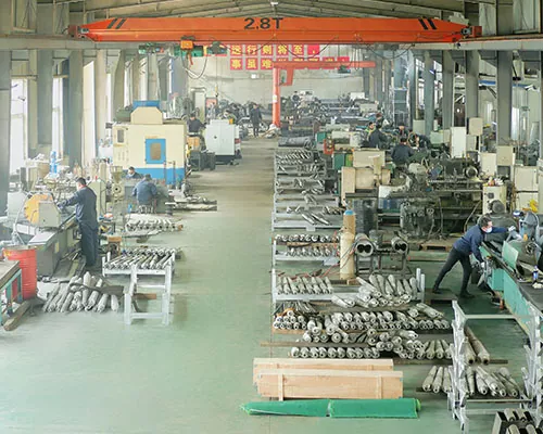
Our factory view: copying a worn sample can reproduce the connection and still preserve the wrong process geometry. If the buyer wants more output, a new resin range or lower melt temperature, say so before the screw is drawn. That turns the project from a copy into a controlled redesign.
For an existing machine, follow the replacement single screw specification guide. It separates dimensions that can be measured from a worn part from process geometry that needs an approved reference.
Check motor power, gearbox ratio and continuous torque together
A high-speed screw still needs torque at the operating point and during difficult starts. Motor power alone does not define what reaches the screw. Gear ratio, efficiency, service factor, cooling, bearing arrangement and the allowed continuous and peak load all matter.
Shaft torque estimate: T = 9550 × P / n
Use power P in kW and rotational speed n in rpm to estimate torque T in N·m at the same shaft. For screw torque, apply the approved gearbox ratio and efficiency rather than mixing motor-side speed with screw-side power.
| Drive field | What to record | Why it matters |
|---|---|---|
| Motor | Rated kW, base speed, current, overload capability and cooling method | Defines the power source and its continuous limit |
| Gearbox | Ratio, rated output torque, service factor, efficiency and lubrication | Converts motor speed into usable screw speed and torque |
| Actual operation | Rpm, current or measured power, torque if available and start history | Shows real duty instead of nameplate capacity |
| Thrust and bearings | Arrangement, condition, lubrication and axial-load basis | High die pressure creates mechanical load beyond simple rotation |
| Connection | Spline, key, thread, shoulder, seal and axial datum | Prevents a process-correct screw from failing the machine fit |
| Protection | Trips, alarms, cooling interlocks and approved load limits | Keeps the acceptance test inside the machine's safe window |
The Nanhaiya single screw extruder product path is useful when the project includes more than the screw. If the old drive data is uncertain, send motor and gearbox nameplates, connection drawings and normal load trends before specifying a higher rpm.
Never use the torque equation as a gearbox approval. It is a first calculation. The gearbox manufacturer or approved machine documentation must provide the continuous and peak limits, service factor, lubrication and permissible operating range.
Separate barrel set temperature from actual melt temperature
The controller shows a heater-zone target and usually a measurement near the barrel wall. The polymer also receives mechanical energy from the rotating screw. At higher surface speed, that mechanical contribution can become large even when the set temperatures do not change.
That is why a lower heater setting does not prove lower melt temperature, and a cooler average does not prove complete melting. Define the melt-temperature location, sensor method, sampling interval and acceptable variation. Check pressure, load and product quality at the same time.
| Acceptance field | Define before the test | Why it belongs in the purchase order |
|---|---|---|
| Barrel zones | Setpoint, actual reading, heater output and cooling response | Shows how the machine holds the thermal profile |
| Melt temperature | Location, sensor, insertion or sampling method, average and variation | Measures the material, not only the metal near a heater |
| Melt pressure | Sensor location, clean and dirty condition, average and variation | Connects screw pumping to screen and die resistance |
| Melt quality | Unmelts, gels, dispersion, surface and approved test method | Prevents output from hiding incomplete or excessive processing |
| Product | Dimensions, wall variation, weight, appearance and relevant product tests | Defines whether the extrusion is saleable |
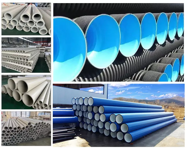
For PE pressure-pipe projects, ISO 4427-1 covers general aspects of PE piping compounds and test parameters. The finished pipe standard and the buyer's own control plan must set the final acceptance requirements. The screw supplier should not replace those product requirements with a generic melt-temperature target.
Our factory position: if the line makes a good product at 90 percent of the advertised rpm and a poor product at 100 percent, the useful limit is the lower point. We manufacture the screw to support a process window. The finished product decides where that window ends.
Choose alloy protection for the actual wear zone
Nanhaiya makes its PE and PP high-speed screws from steel sourced directly from steel mills and formed to support density and toughness. The current bimetallic specification uses nickel-based alloy and tungsten alloy, with alloy length over 400 mm, depth from 2 to 3 mm and hardness from HRC58 to 65. The final surface can be customized for wear and corrosion duty.
Those numbers belong on a drawing, not only a product page. Define where the alloy starts and stops, what the depth means after finishing, where hardness is tested, which Rockwell scale and method apply, and what barrel surface will run against it.

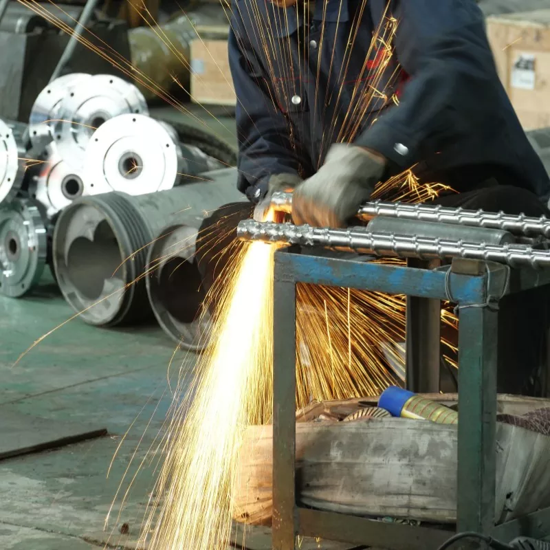
Clean virgin PE or PP and a filled or contaminated recycled blend do not create the same wear environment. When filler, glass, hard contamination or corrosive additives are present, compare the screw and barrel as a pair. A harder flight can still perform poorly inside an enlarged or incompatible barrel.
| Wear question | Evidence needed | Order decision |
|---|---|---|
| Where did the old screw lose diameter? | Axial screw OD map and cleaned surface photos | Place alloy where the load and wear actually occur |
| Is the barrel still round and within the approved bore? | ID readings by station and angular direction | Decide screw-only or matched screw-and-barrel replacement |
| Is the damage abrasive, corrosive or mechanical? | Material recipe, residue, temperature, alignment and score pattern | Select material or correct the mechanical cause first |
| Will the surface pair run safely? | Screw alloy, barrel lining, finish and clearance | Approve the counterface and working clearance together |
| How will the layer be accepted? | Drawing, process record, hardness method and dimensional plan | Turn a sales description into inspectable requirements |
Use the nitrided versus bimetallic single screw guide for treatment selection, and the single screw and barrel wear measurement guide before deciding whether the barrel can remain in service.
PE and PP high-speed single screw RFQ checklist
A strong RFQ lets the screw factory distinguish a mechanical copy from a performance redesign. Mark unknown items as unknown. Do not invent a dimension or operating value to make the form look complete.
- Machine maker, model and serial or version
- Current screw and barrel drawings
- Fresh screw OD and barrel ID wear map
- Exact PE or PP maker and grade
- MFR or MVR value with temperature and load
- Pellet, powder, flake, regrind or blend
- Recycled percentage and batch variation
- Filler, fiber, pigment and additive levels
- Moisture result, method and drying process
- Product, die and screen-pack information
- Normal and required saleable output
- Normal, minimum and maximum screw rpm
- Motor nameplate and actual operating load
- Gearbox ratio, torque rating and service data
- Barrel setpoints and measured melt temperature
- Clean and dirty melt pressure
- Heating, cooling and feed-throat controls
- Product dimensions and acceptance standard
- Current defects, scrap and operating history
- Required material and inspection documents
- Destination, quantity and required delivery date
- Installation and commissioning support needed
Nanhaiya's current product information lists standard-screw delivery at 24 to 48 hours and customized-screw delivery at 30 to 40 days. Treat the lead time as an order field: confirm the exact drawing, quantity, material, surface process, inspection documents, packing and delivery term before the purchase order.
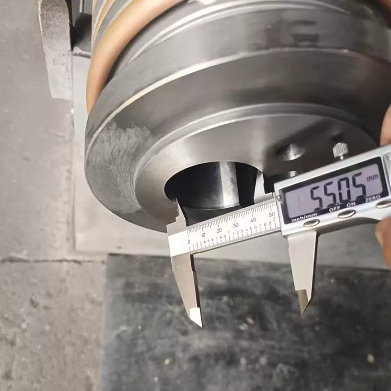
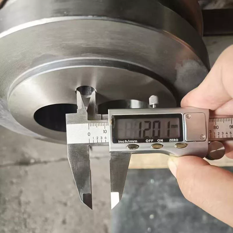
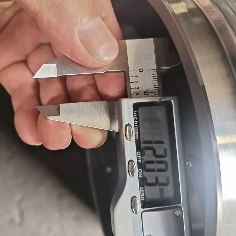
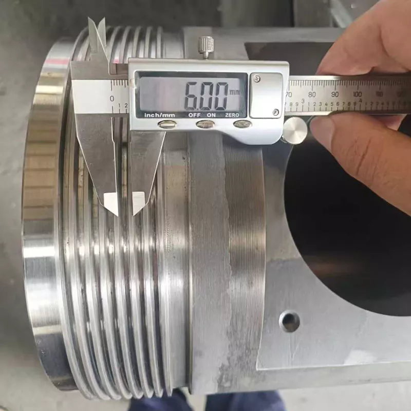
Our factory view: dimensional photographs are useful evidence, but a caliper display is not the specification. We need the approved drawing, tolerance, instrument range and inspection location. That is what makes the result repeatable.
Nanhaiya lists pre-sales diagnosis based on material, machine and capacity, followed by matching of diameter, L/D, groove depth and material. The service page also covers installation guidance, troubleshooting, maintenance, 24-hour response and solutions within 48 hours. Confirm the project-specific service scope and warranty in the contract.
Build the acceptance test before production starts
The acceptance test should be agreed while the drawing is being approved, not after the screw reaches the line. Use the same resin lot where possible, define material preparation, bring the line to a stable condition and collect synchronized process and product data.
- Freeze the test material. Record maker, grade, batch, MFR or MVR condition, moisture, recycled content and additives.
- Define the machine state. Record screw and barrel identity, die, screen pack, heaters, cooling, gearbox oil and sensor calibration status.
- Run agreed operating points. Include a normal point, target point and any approved upper point rather than jumping directly to maximum rpm.
- Wait for stability. Agree the stabilization time and the conditions that restart the clock after a setting change.
- Record synchronized data. Capture rpm, gross and saleable output, power, load, melt temperature, pressure, zone response and product results over the same interval.
- Apply stop limits. Stop when load, pressure, temperature, vibration, product quality or another approved safety boundary is reached.
- Approve the baseline. Save the accepted settings, averages, variation, sample results and inspection documents for future troubleshooting.
| Acceptance item | Record | Pass basis |
|---|---|---|
| Saleable output | kg/h after scrap and rejected product | Meets the agreed value at the named product and quality |
| Specific energy | kWh/kg with the measurement boundary identified | Meets the agreed comparison using the same boundary |
| Melt temperature | Average, variation, location and method | Inside the resin and product control window |
| Melt pressure | Average, variation, sensor location and screen state | Stable and inside the line's approved limit |
| Drive duty | Motor input, load, gearbox condition and alarms | Inside continuous limits with agreed margin |
| Product quality | Dimensions, appearance, defects and required tests | Passes the buyer's product specification |
| Thermal control | Zone actuals, heater output and cooling response | No uncontrolled drift or repeated saturation |
| Stability | Duration, sampling interval and variation | Holds the accepted condition for the agreed period |
The factory standard I recommend: accept the screw at the point where output, quality and machine duty are all stable. Do not reward a test for producing more kilograms if those kilograms are hotter, less uniform, off-size or made with an overloaded drive.
After commissioning, keep the accepted condition as the baseline. If output later falls at the same rpm or load rises at the same output, compare the current data with that baseline before changing multiple settings. Then inspect wear, feeding, filtration and die resistance in a controlled order.
Frequently asked questions
What data is needed to quote a PE or PP high-speed single screw?
Send the polymer maker and grade, PE or PP type, MFR or MVR with test temperature and load, feed form, recycled content, filler and additive levels, moisture data, product and die, normal and maximum output, screw diameter and L/D, rpm range, motor and gearbox data, melt temperature, melt pressure, motor load, barrel drawing, present wear measurements and the acceptance targets.
Does higher screw rpm always produce more PE or PP output?
No. Output can stop rising in proportion to rpm when feeding, melting, drive torque, cooling, filtration, die resistance or downstream equipment reaches a limit. Compare stable operating points and stop increasing speed when product quality, melt temperature, pressure, load or safety reaches its approved boundary.
How can I compare screw speed between different diameters?
Convert rpm to screw surface speed with v equals pi times D times N divided by 60, where D is screw diameter in metres and N is rpm. A 65 mm screw at 150 rpm is about 0.51 m/s, while a 90 mm screw at 110 rpm is about 0.52 m/s. Similar surface speed does not guarantee similar output because geometry and line resistance still differ.
What alloy protection does Nanhaiya publish for its PE and PP high-speed screw?
Nanhaiya publishes a bimetallic construction using nickel-based alloy and tungsten alloy, with alloy length over 400 mm, depth from 2 to 3 mm and hardness from HRC58 to 65. The exact alloy, protected location, depth basis, hardness method and matching barrel surface should be fixed in the order drawing and inspection plan.
How should a buyer verify the published efficiency improvement?
Use an agreed comparison test with the same resin lot, product, die, screen condition, quality limits, stabilization time and electrical measurement boundary. Record saleable output, actual power, specific energy, melt temperature, pressure, motor load and reject rate. Do not compare only the highest rpm or nameplate motor power.
Can a high-speed replacement screw be installed in the old barrel?
Only after the barrel bore, straightness, alignment, surface construction and screw-to-barrel clearance have been checked. An enlarged, oval or scored barrel can reduce pumping efficiency or damage the new screw. The replacement drawing must also confirm the gearbox connection, thrust interface, feed opening and downstream dimensions.
Which PE and PP material data matter most for screw design?
Identify the exact grade and family, density or material designation, MFR or MVR test condition, pellet or recycled-feed form, bulk consistency, moisture, recycled percentage, filler, pigment, stabilizer and any permitted grade changes. MFR or MVR is a useful quality-control reference, but it does not replace processing data at extrusion shear rates.
What should be recorded during a high-speed single screw acceptance test?
Record resin lot and preparation, actual rpm, saleable output, melt temperature and variation, melt pressure and variation, motor input and load, gearbox condition, barrel-zone heating and cooling response, product dimensions and defects, scrap, screen condition, stabilization time and each agreed operating point. Keep the accepted data as the future production baseline.
Sources checked for this guide
- Nanhaiya: PE PP High Speed Single Screw
- Nanhaiya: Single Screw category and model range
- Nanhaiya: Extruder Single Screw Barrel
- Nanhaiya: LDPE HDPE Film Single Screw
- Nanhaiya: Production Equipment
- Nanhaiya: Service Process
- ISO 11443:2021: Plastics, determination of fluidity using capillary and slit-die rheometers
- ISO 1133-1:2022: MFR and MVR by the standard method
- ISO 15512:2019: Determination of water content
- ISO 17855-1:2014: Polyethylene moulding and extrusion materials
- ISO 19069-1:2015: Polypropylene moulding and extrusion materials
- ISO 4427-1:2019: PE piping systems for water supply and pressure drainage
Nanhaiya product, model, construction, service and delivery data were taken from the live company website. ISO pages were used for the scope of the named standards. Project-specific performance and acceptance values must be fixed in the approved quotation, drawing and test plan.