
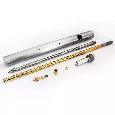
A screw tip is small enough to be treated like a spare part, yet precise enough to decide whether every shot starts with the same volume of melt. Buy it as a matched flow and sealing assembly, not as a threaded metal point.
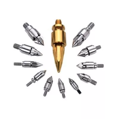
Quick answer
Choose an injection molding screw tip by four things: the non-return valve design, the exact screw and barrel interface, the processed resin and filler, and the wear pattern of the existing assembly. Machine model alone is not enough when versions, previous repairs or non-standard screws may exist.
For a replacement order, send the original drawing when available, then verify the thread, shoulder, tip length, ring travel, seat, outside diameter and melt passages against the actual machine. A good quotation starts with geometry. Material and surface treatment come next.
The screw tip controls flow in both directions
During screw recovery, the non-return valve opens and lets molten polymer pass toward the front of the screw. At the start of injection, it closes so screw movement and pressure act on the shot instead of pushing melt backward along the screw.
This is why the screw tip, check ring and seat belong to the process, not only to maintenance. ENGEL's non-return valve tutorial describes the same two operating states and links closing behavior directly to injection repeatability.
Our factory view: the most expensive screw-tip mistake is rarely the difference between two material grades. It is a part that threads onto the screw but does not travel, seal or align correctly. A successful fit test is more valuable than a long list of sales adjectives.
Choose the assembly around the molding duty
The right design must open freely during recovery, close predictably during injection and avoid excessive restriction in the melt path. It must also survive the resin's abrasive, adhesive and corrosive load without damaging its mating surfaces.
| Purchasing question | Why it changes the screw tip | What to send the supplier |
|---|---|---|
| What resin is being molded? | Viscosity, lubricity, degradation sensitivity and corrosion duty affect flow passages, material and surface treatment. | Exact resin grade, color system, flame retardant and normal processing range. |
| Is the resin reinforced or filled? | Glass fiber, mineral filler and reclaimed contamination can accelerate abrasive wear at the ring, seat and melt passages. | Filler type, weight percentage and whether it changes by product. |
| How precise must the shot be? | Thin-wall, multi-cavity and tight-weight parts expose small changes in valve closing and leakage. | Part weight, cavity count, shot-weight tolerance and recent trend data. |
| What is the present valve style? | Sliding ring, ball-check and other designs have different flow areas, travel and closing behavior. | Original part number, drawing, photos and the complete removed assembly. |
| Has the screw been replaced before? | A machine model may no longer identify the installed thread, tip length or seat geometry. | Current screw drawing and direct measurements, not only the machine nameplate. |
| Why is the part being replaced? | A broken thread, eroded flow path and leaking ring do not point to the same corrective action. | Wear photos, process symptoms, maintenance history and failed dimensions. |
Nanhaiya offers standard and customized thread patterns, plus reverse-flow tip options for special polymers. The selected part can be matched with an injection molding screw or supplied as part of the broader injection molding and extrusion spare-parts range.
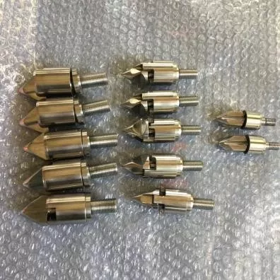
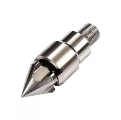
Read process signals before removing the assembly
A variable cushion, drifting shot weight or poor transfer repeatability can point to valve leakage, but none of them proves it alone. Resin changes, feed instability, temperature control, barrel wear, air in the melt, pressure settings and mold conditions can create similar symptoms.
ENGEL recommends checking the non-return valve, screw and plasticizing barrel when the melt cushion fluctuates. The same troubleshooting guidance connects cushion and shot-weight variation with process settings and component wear.
| Observed signal | Possible screw-tip connection | Check before ordering |
|---|---|---|
| Cushion position varies from shot to shot | The ring may close at a different point or leak after seating. | Trend actual position, pressure and shot weight under a stable process. |
| Part weight drifts while settings stay fixed | Backflow can reduce the effective volume delivered to the mold. | Rule out feed, temperature, material and mold-cavity causes. |
| Short shots appear intermittently | The valve may not seal repeatably, especially after recovery changes. | Compare transfer response and run the machine maker's approved valve test. |
| Recovery becomes restricted | A damaged ring, deposit or undersized flow path may resist forward melt flow. | Inspect for free movement, deposits, galling and passage obstruction. |
| Black specks follow a material change | Dead spots or damaged surfaces may retain and release degraded polymer. | Inspect the full melt path, nozzle, screw front and cleaning procedure. |
| Metallic noise or ring seizure | Galling, deformation, misalignment or foreign material may be present. | Stop and inspect under the machine maker's safe maintenance procedure. |
Once the assembly is removed, examine the outside diameter of the check ring, both end faces, the seating surface, tip body, melt passages and thread. An ARBURG technical article identifies abrasion, adhesion and corrosion as wear mechanisms and shows that wear at the ring diameter, end face and sealing seat can change ring travel and cushion stability.
Do not diagnose a check ring by adding holding pressure until the part fills. A setting change can hide leakage without correcting it. Capture a stable baseline, follow the machine maker's approved test method and inspect the hardware before changing the replacement specification.
Replace one part only when the mating parts are still good
A check ring can be replaced by itself when its mating tip and seat remain within the approved dimensions, the sealing surfaces are sound, and the new ring can move freely through its complete travel. This is the lower-cost repair, but only when the inspection supports it.
Replace the matched tip, ring and seat when several surfaces show wear, a ring has seized or galled against another component, the old parts have been mixed across machines, or no reliable original dimensions remain. Combining one new sealing part with two worn mating parts can create a new leakage path.
Our factory view: a worn sample is evidence, not a master drawing. If we copy an eroded seat, shortened ring or damaged thread exactly, the new part can reproduce the old problem with a cleaner surface. We reconstruct the intended relationship from the drawing, mating components and unworn reference points.
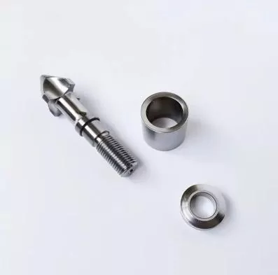
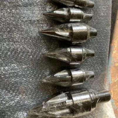
Nanhaiya injection molding screw tip data
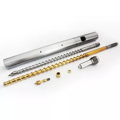
The Nanhaiya injection molding screw tip is built as the interface between the screw and nozzle-side melt path. It is available for different screw diameters and injection machine brands, with custom threads and component geometry for replacement work.
| Specification | Nanhaiya product data | Purchasing relevance |
|---|---|---|
| Base material | D2 | Record the actual material on the quotation and inspection documents. |
| Hardness | HRC45-62 | The selected value must match the heat treatment, wear duty and mating materials. |
| Straightness | 0.02 mm/m | Geometry and alignment matter at the screw-front interface. |
| Armored face | Bimetallic | Provides a wear-resistant option at exposed working surfaces. |
| Glass-fiber configurations | 30% / 60% | State the actual glass-fiber percentage and resin grade in the RFQ. |
| Part weight | 1 kg | Product-page reference value; final weight follows the approved geometry. |
| Manufacturing route | CNC machining, heat treatment and precision polishing | These operations control form, surface condition and finished fit. |
| Standard applications | PE, PP, ABS and PVC thermoplastic molding | Also send additives, colorants, recycled content and filler data. |
For the complete plasticizing unit, Nanhaiya also manufactures mutant injection molding screws, gradual injection molding screws and matching replacement barrels. The adjacent injection nozzle can be reviewed at the same time when leakage, alignment or melt-flow problems extend beyond the screw tip.
Dimensions that decide whether the part will fit
A machine maker and model can narrow the search, but it cannot replace a drawing. Model families may use several injection-unit sizes, and a machine may already carry a replacement screw that differs from its original build.
- Identify the installed screw. Record machine maker, model, injection-unit designation, screw diameter, serial information and any previous screw replacement.
- Define the thread completely. Include major and minor diameter, pitch, thread direction, thread length, start position, relief and shoulder location.
- Measure the axial stack. Record overall tip length, ring length, seat length, ring travel and every shoulder that controls closing position.
- Measure radial interfaces. Record tip body diameter, ring outside and inside diameter, seat diameters, barrel bore reference and required working clearance.
- Map the melt path. Show flute count, passage width, passage depth, nose profile and any radius that affects flow or cleaning.
- Mark sealing and wear surfaces. Identify which faces contact during closing and which dimensions are measured from unworn references.
Do not hide uncertainty inside a tolerance. If the old surface is worn, label the measured value as an actual worn dimension. Keep the proposed finished dimension separate. That distinction lets engineering correct the part instead of approving a precise copy of the damage.
Inspect the replacement before it enters production
Incoming inspection should verify identity, dimensions and movement before the assembly is exposed to heat and pressure. Keep the approved drawing, material record and inspection result under the same part number.
- Part number and drawing revision match the purchase order
- Material and heat-treatment records match the quotation
- Critical diameters and axial lengths are within drawing tolerance
- Thread gauges or mating checks confirm the connection
- Check ring travels freely without visible rocking or seizure
- Ring and seat contact the intended sealing surfaces
- Melt passages are clean, smooth and free of burrs
- Polished surfaces show no handling damage or coating defects
- Assembly direction and component order are documented
- Baseline shot weight and cushion are recorded after installation
After installation, use an approved startup procedure and compare the process with the retained baseline. A new tip may change recovery, decompression response or valve closing behavior, so do not assume every old setting must remain untouched.
What the factory must control
Screw-tip quality comes from the relationship between parts. Thread concentricity, shoulder position, ring travel, sealing-face geometry, flow-path finish and heat-treatment condition must work together. One impressive hardness number cannot compensate for an incorrect stack length or a rough sealing surface.
Nanhaiya's production equipment includes CNC saws with feed error at or below 0.1 mm, CNC lathes for workpieces up to 6 m, and drilling and milling equipment with 0.02 mm positioning accuracy. Five-axis machining is used for irregular flights and special flange structures.
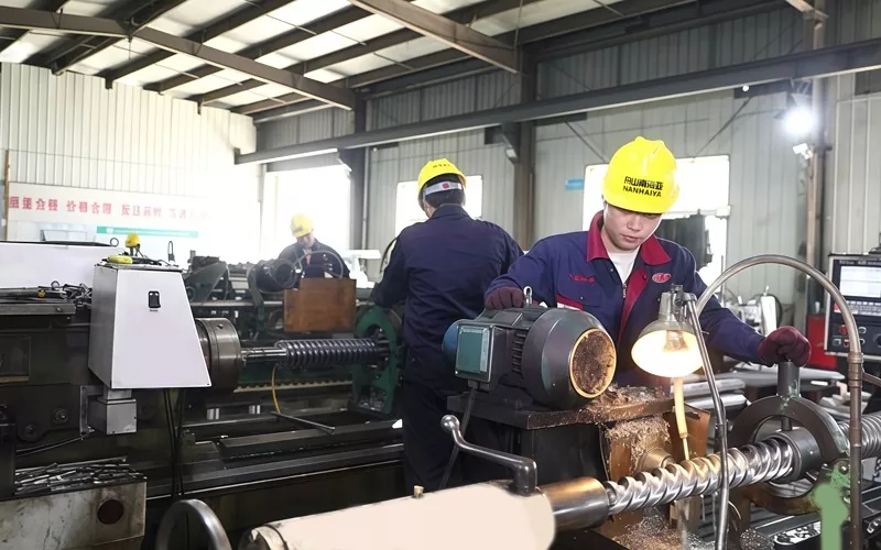
For buyers, the practical question is not whether a supplier owns a machine tool. Ask how the drawing is reviewed, which dimensions are inspected, how material and heat treatment are traced, and how the finished ring movement is checked. Nanhaiya provides pre-sales drawing review and technical support through its service team.
RFQ checklist for a replacement screw tip
Send one clear package instead of a series of partial messages. The following information lets the supplier decide whether the job is a standard replacement, a reverse-engineered component or a redesign.
- Machine maker, model, serial number and injection-unit size
- Installed screw diameter and screw drawing
- Original screw-tip part number and drawing revision
- Complete old assembly with parts kept in order
- Photos from the front, side, thread and sealing faces
- Thread, shoulder, ring, seat and passage dimensions
- Resin grade, filler type and filler percentage
- Colorant, recycled content and corrosive additives
- Normal melt temperature and shot size
- Part weight, cavity count and accepted variation
- Cushion, transfer and recovery trend before removal
- Observed wear, failure mode and quantity required
If the drawing is missing, mark every measured surface and photograph the measurement setup. Do not send a single outside diameter and ask the factory to infer the thread, seat and travel from it.
Frequently asked questions
What does an injection molding screw tip do?
The screw tip assembly carries a non-return valve. It opens during screw recovery so melt can move in front of the screw, then closes during injection to limit backflow and transfer pressure into the mold.
What are the signs of a worn check ring or screw tip?
Common process signals include a variable melt cushion, inconsistent shot weight, poor pressure repeatability, short shots after other causes have been excluded, and a longer or less stable transfer response. Confirm wear with a controlled leak test and dimensional inspection.
Can I order a replacement screw tip by machine model only?
The machine maker and model are useful starting points, but a reliable replacement order should also include the screw diameter, thread and shoulder dimensions, tip length, check ring and seat dimensions, flow path, resin, filler content, drawing and clear photos.
Should I replace only the check ring or the complete screw tip assembly?
Replace only the worn component when the mating tip, seat and thread remain within the approved dimensions and surface condition. Replace the matched assembly when several sealing surfaces are worn, dimensions are uncertain, or mixed old and new parts cannot produce reliable movement and sealing.
Which material does Nanhaiya use for injection molding screw tips?
Nanhaiya offers D2 injection molding screw tips with a published hardness range of HRC45-62, 0.02 mm/m straightness and a bimetallic armored-face option. The final configuration is matched to the resin, filler, machine interface and wear duty.
Does a harder screw tip always last longer?
No. Hardness is only one part of wear performance. Alloy chemistry, heat treatment, corrosion resistance, mating materials, surface finish, alignment, clearance and the processed resin all affect service life.
What should I send Nanhaiya for a screw tip quotation?
Send the machine maker and model, screw diameter, resin and filler percentage, original part number or drawing, complete mating dimensions, photos from several angles, wear symptoms, shot-weight trend and the quantity required.
Commercial disclosure: Nanhaiya manufactures the injection molding screw tips and related components linked in this guide. Technical recommendations should be applied with the machine maker's safety procedures and the approved project drawing.