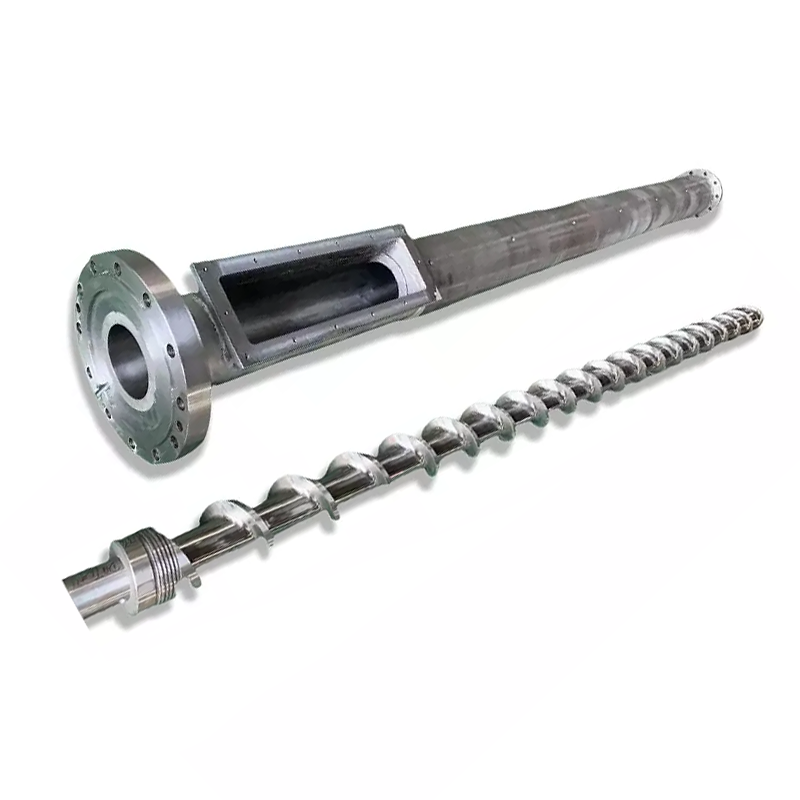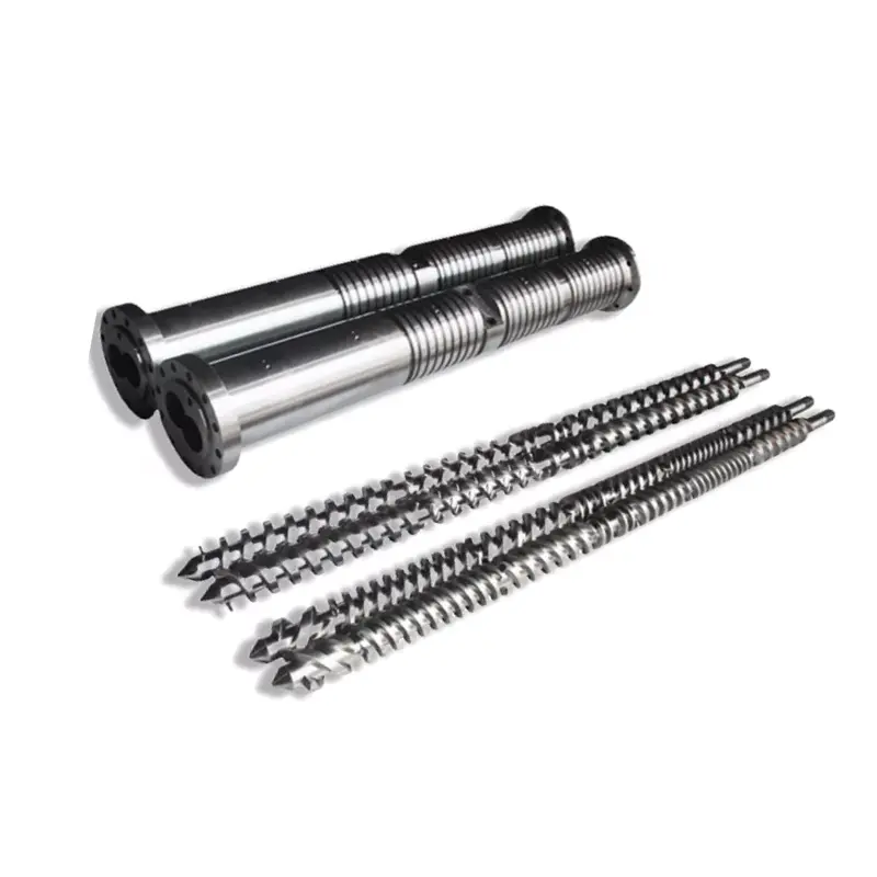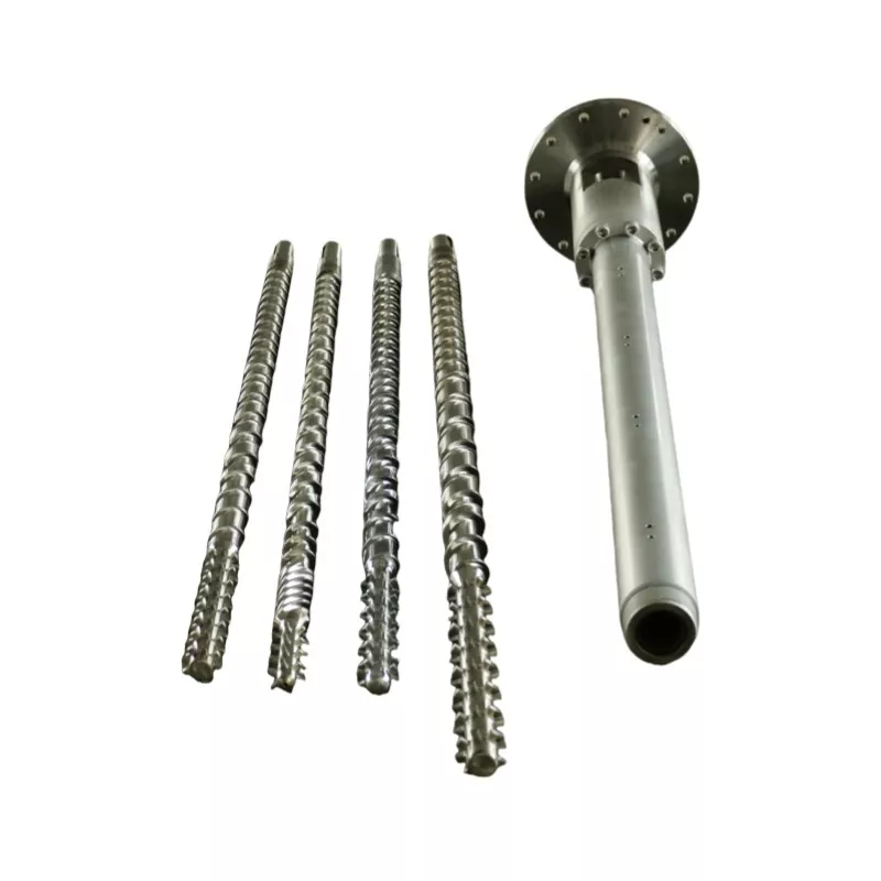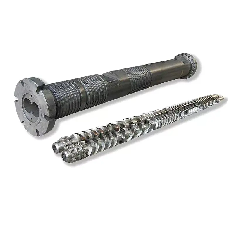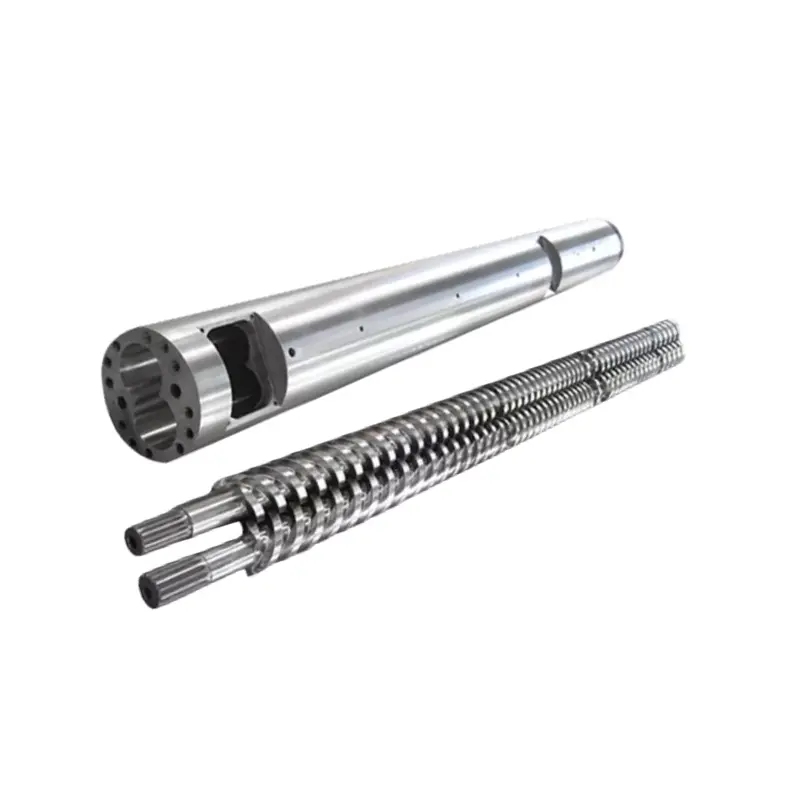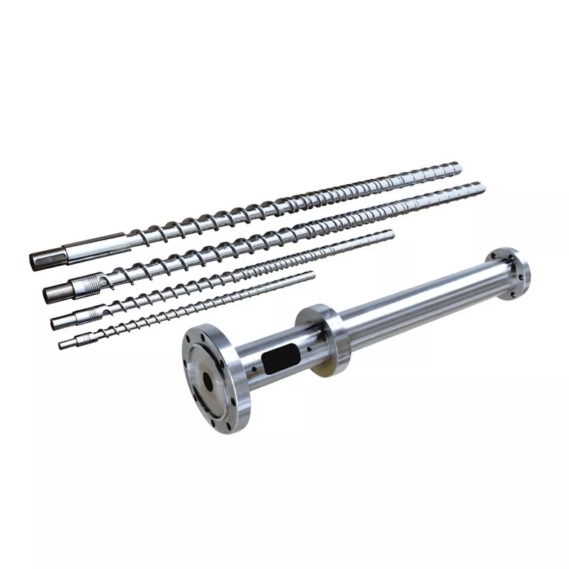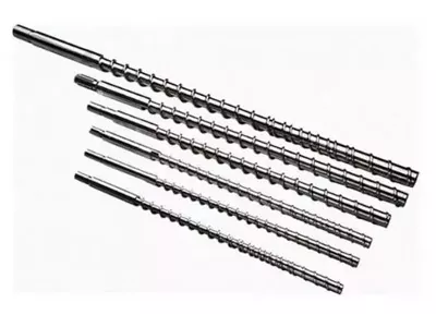

Nanhaiya uses "mutant" for an abrupt, step-change compression screw. Its short transition melts crystalline materials quickly. A gradual screw spreads compression over much more of the screw length, which suits a gentler plasticizing path. Resin family is the starting point. The actual grade, shot use, recovery data, melt quality and wear duty decide the order.

Quick answer
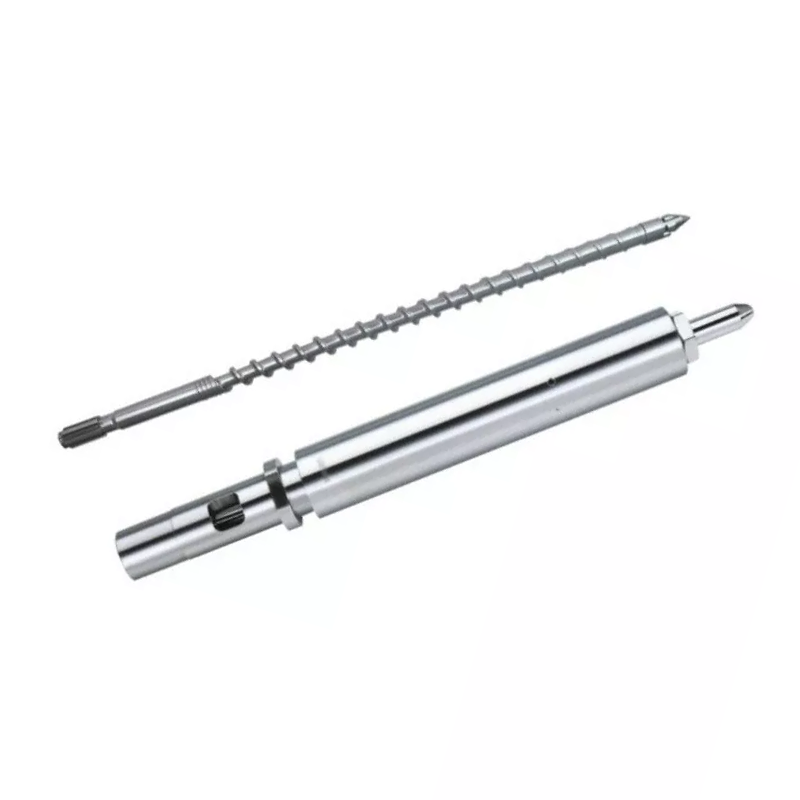
Choose a mutant or abrupt injection molding screw as a starting point for crystalline or semi-crystalline materials that benefit from rapid compression and melting. Nanhaiya lists PE, PP, PA, POM and PTFE. Its mutant compression section occupies about 5% to 15% of total screw length.
Choose a gradual screw as a starting point for amorphous or heat-sensitive materials that need a smoother transition. Nanhaiya lists rigid PVC, PS, PC, PSU and ABS. Its gradual compression section normally occupies 40% to 60% of total length, with about 50% described as typical. Confirm either choice with the actual grade, filler, moisture, shot use, recovery time, melt condition and molded-part acceptance.
What Nanhaiya means by mutant and gradual
The word "mutant" on our product page does not mean a repaired or modified screw. It describes an abrupt compression profile, sometimes called a step-change design. A deep feed channel changes to a shallow metering channel over a short compression section.
A gradual screw makes the same general change over a much longer distance. Its channel depth decreases continuously, so material sees compression and shear build over more screw length.
| Geometry | Nanhaiya compression-section range | Channel-depth change | Plasticizing character |
|---|---|---|---|
| Mutant or abrupt | About 5% to 15% of total screw length | Distinct, short transition from deep to shallow | Fast compaction and intense shear over a short distance |
| Gradual | About 40% to 60%, with roughly 50% typical | Slow, continuous reduction through a long transition | Gentler energy conversion and progressive shear |
Our factory view: the two screws can have the same diameter, overall length and drive connection while behaving differently inside the barrel. That is why a worn sample and a machine model do not tell us whether the old process profile should be copied.
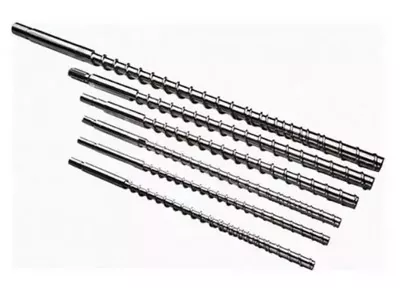
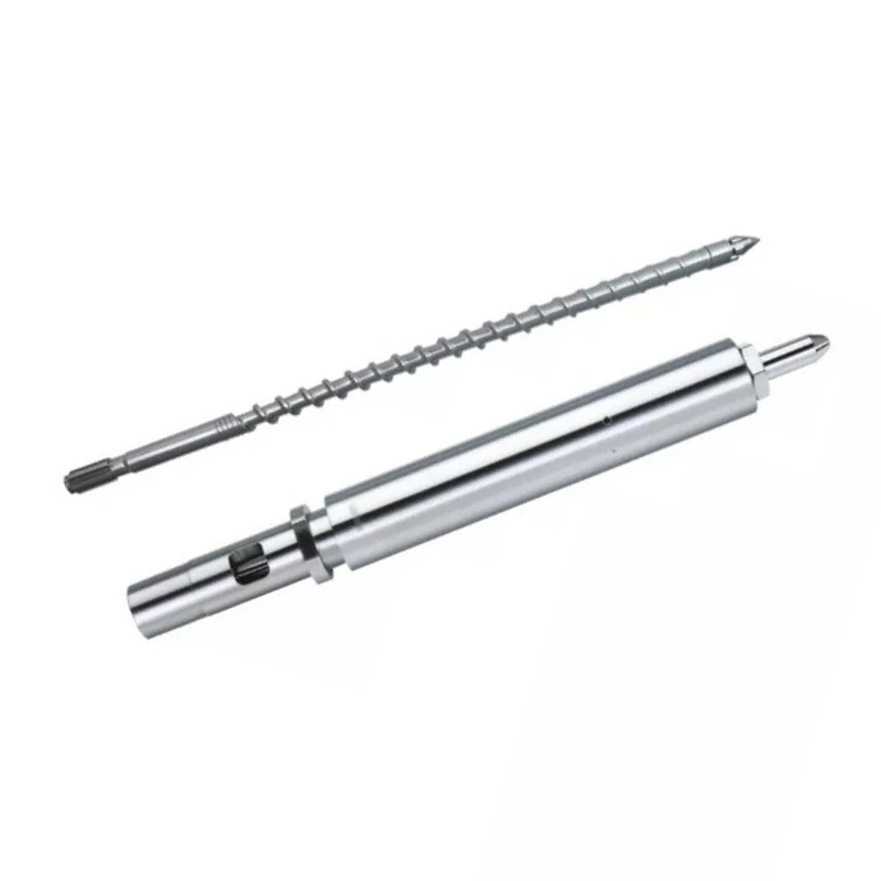
The Nanhaiya injection molding screw category contains both types. For the broader screw, barrel and resin selection process, use our injection molding screw barrel selection guide.
Mutant vs gradual injection molding screw at a glance
The material list below is a selection direction, not a substitute for the resin maker's data. Filled PA can put more wear into the same geometry. Recycled PP can feed and recover differently from virgin PP. Flame-retarded ABS can narrow the thermal window compared with an unfilled grade.
| Decision field | Mutant or abrupt screw | Gradual screw |
|---|---|---|
| Compression section | Short, about 5% to 15% of screw length | Long, about 40% to 60% of screw length |
| Channel profile | Depth changes quickly at a defined transition | Depth decreases steadily through the transition |
| Energy input | More concentrated compression and shear | Energy input develops over a longer distance |
| Melting behavior | Fast plasticizing for materials suited to the abrupt profile | Gentler plasticizing for materials that need a smoother path |
| Nanhaiya resin examples | PE, PP, PA, POM and PTFE | Rigid PVC, PS, PC, PSU and ABS |
| Known trade-off | Initial melt may need more work on temperature uniformity | Longer transition may not deliver the fastest recovery for every crystalline grade |
| Process checks | Back pressure, screw speed, recovery, melt variation and degradation | Recovery, residence, thermal history, mixing and part quality |
| Wrong reason to choose | "We need a faster cycle" without melt and part data | "The material is heat sensitive" without the exact grade and temperature window |
Nanhaiya's mutant product page lists 15% to 30% higher plasticizing efficiency than a gradual screw for the described crystalline-plastic duty. That comparison becomes useful to a buyer only when the resin, shot, recovery definition, screw speed, back pressure and accepted melt condition are fixed. We would put those conditions in the test plan before putting the percentage in a purchase guarantee.
Short selection rule: use polymer structure to choose the first geometry to evaluate. Use production evidence to approve it. If a screw shortens recovery but creates temperature variation, black specks, splay or shot-weight drift, it has not improved the process.

Choose by the real resin, not one polymer acronym
A resin name gets the conversation started. It does not finish the drawing. The grade, viscosity reference, reinforcement, flame retardant, color, recycled content and moisture condition can change plasticizing, wear and recovery.
ISO 1133-1:2022 defines MFR and MVR tests at specified temperature and load. It also notes that these tests use much lower shear rates than normal processing and are mainly quality-control tools. Send the value and test condition, but do not ask the screw maker to predict the whole cycle from MFR alone.
Crystalline starting point
For PE, PP, PA, POM and PTFE, Nanhaiya starts with the mutant profile. Then we check the exact grade, melting behavior, filler, moisture and the machine's recovery data.
Amorphous starting point
For rigid PVC, PS, PC, PSU and ABS, Nanhaiya starts with the gradual profile. The long transition supports a smoother plasticizing path, but the actual thermal window still comes from the material supplier.
Mixed production
If one machine runs both groups, list production share and the hardest quality problem for each grade. A general-purpose screw may be practical, but it should be approved as a compromise.
| Material field | What to send | Why it matters to the profile |
|---|---|---|
| Exact identity | Supplier, commercial grade, polymer family and approved substitutes | Different grades under one acronym can have different viscosity and thermal behavior |
| Flow reference | MFR or MVR value, temperature, load and sample condition | Allows controlled comparison between production lots and candidate grades |
| Reinforcement | Glass, carbon or mineral type and weight percentage | Changes wear, energy input, mixing and surface-system choice |
| Recycled fraction | Percentage, source, batch variation and contamination | Can change feed consistency, degradation history and recovery |
| Additives | Flame retardant, pigment, stabilizer, lubricant and masterbatch | Can change corrosion, dispersion and thermal sensitivity |
| Water content | Result, method, dryer setting and material handling | Separates screw problems from moisture-related splay or degradation |
| Supplier window | Recommended melt, mold and drying conditions | Creates the allowable test window for the new screw |
ISO 15512:2019 covers water-content methods for plastics and specifically includes PA, PC, PP, PE, PTFE and PVC among the materials suitable for one of its methods. Use the method required by the resin or quality system. A dryer setpoint by itself is not a moisture result.
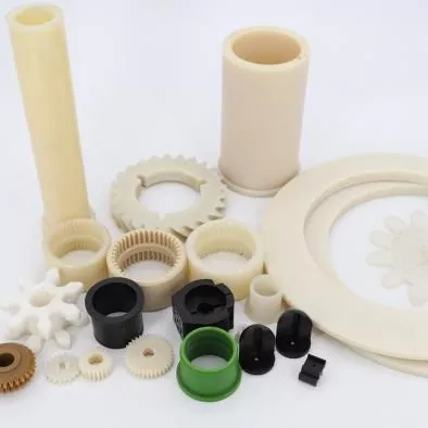
What I ask before choosing a profile: which grade controls your rejects? A machine may run PP most of the week, but the difficult glass-filled PA job can determine the surface system and the acceptable recovery window. Production share matters, and so does the most demanding part.
How the compression profile changes plasticizing
During screw recovery, pellets enter the feed section while the rotating screw moves backward. Channel depth, barrel heat, friction, back pressure and screw speed determine how that material compacts, melts and mixes before the next shot.
The mutant screw concentrates much of that change in a short zone. This can accelerate plasticizing for a suitable crystalline grade. The same intensity can leave more temperature variation if screw speed and back pressure are pushed without checking the melt.
The gradual screw uses more length for the transition. Material sees a steadier reduction in channel depth, which gives amorphous and heat-sensitive grades a gentler path. It does not excuse long residence time, poor drying, an oversized barrel or excessive back pressure.
| Process observation | What it may mean | What to check before changing the screw |
|---|---|---|
| Recovery is slow but part quality is stable | The screw may have limited plasticizing capacity, or the cycle may be set conservatively | Actual shot, cooling time, screw speed, back pressure, heater output and drive load |
| Recovery is fast but melt variation rises | Energy may be entering too quickly or mixing may be incomplete | Melt-temperature method, screw speed, back pressure, shot variation and defects |
| Black specks increase after a speed change | Shear heat, residence, deposits or wear may be involved | Material history, purge result, setpoints, actual melt, screw and barrel condition |
| Splay appears on PA or PC | Moisture, degradation, gas or plasticizing conditions may be involved | Measured water content, drying records, residence, decompression and melt condition |
| Cushion or shot weight drifts | Non-return valve, clearance, feed consistency or plasticizing may be unstable | Screw tip, barrel bore, recovery trend, feed and process repeatability |
| Motor load rises after adding filler | The compound changed torque and wear duty | Filler level, actual power, screw speed, back pressure and surface system |
Do not use back pressure to repair the wrong geometry indefinitely. Back pressure can improve mixing and melt preparation, but it also adds work, recovery time and heat. Record the setting and result. If the acceptable process window becomes too narrow, review the screw profile.
When recovery is the main complaint, follow our injection molding screw recovery diagnostic before ordering a replacement. That page separates material, settings, drive, wear and screw-capacity causes.
Match screw diameter and barrel size to the real shot
Compression profile does not fix an oversized or undersized plasticizing unit. Nanhaiya's current injection selection guide uses 35% to 70% of maximum shot capacity as the working range for the actual shot. Use the machine maker's approved calculation, material density and full plasticizing-unit data before applying that range.
The product pages publish the same 23 common screw and barrel combinations for both mutant and gradual geometries. These are range references. A replacement order still needs every interface, zone, thread, shoulder and barrel dimension on the approved drawing.
| Published injection amount | Screw diameter × length | Barrel diameter × length |
|---|---|---|
| 30 to 90 g | Φ30 × 900 mm | Φ85 × 860 mm |
| 60 to 125 g | Φ35 × 910 mm | Φ85 × 860 mm |
| 100 to 150 g | Φ38 × 935 mm | Φ95 × 900 mm |
| 125 to 160 g | Φ40 × 980 mm | Φ95 × 910 mm |
| 125 to 300 g | Φ42 × 1,030 mm | Φ105 × 1,110 mm |
| 250 to 400 g | Φ45 × 1,210 mm | Φ115 × 1,165 mm |
| 300 to 500 g | Φ50 × 1,300 mm | Φ125 × 1,260 mm |
| 450 to 600 g | Φ55 × 1,335 mm | Φ130 × 1,320 mm |
| 500 to 700 g | Φ56 × 1,350 mm | Φ130 × 1,350 mm |
| 500 to 700 g | Φ60 × 1,380 mm | Φ140 × 1,350 mm |
| 650 to 800 g | Φ65 × 1,415 mm | Φ150 × 1,420 mm |
| 700 to 1,000 g | Φ70 × 1,790 mm | Φ160 × 1,685 mm |
| 80 to 125 g | Φ75 × 1,825 mm | Φ170 × 1,725 mm |
| 100 to 150 g | Φ80 × 2,000 mm | Φ180 × 1,805 mm |
| 125 to 200 g | Φ85 × 2,300 mm | Φ190 × 1,900 mm |
| 200 to 300 g | Φ90 × 2,700 mm | Φ210 × 2,000 mm |
| 250 to 500 g | Φ100 × 2,600 mm | Φ230 × 2,405 mm |
| 300 to 600 g | Φ110 × 2,600 mm | Φ256 × 2,590 mm |
| 400 to 1,000 g | Φ120 × 2,800 mm | Φ256 × 2,800 mm |
| 600 to 800 g | Φ130 × 3,010 mm | Φ256 × 2,970 mm |
| 800 to 1,000 g | Φ145 × 3,010 mm | Φ256 × 3,200 mm |
| 1,000 to 1,500 g | Φ160 × 3,500 mm | Φ270 × 3,200 mm |
| 1,300 to 2,500 g | Φ170 × 3,415 mm | Φ317 × 3,380 mm |
Our factory view: the table helps identify Nanhaiya's published manufacturing range. It does not identify your replacement. The same nominal injection amount can appear with different machine versions, resin-density assumptions, screw tips and interfaces. We release the drawing from measurements and approved machine data.
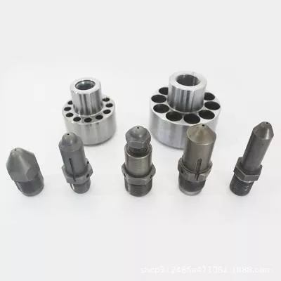
The screw tip controls melt sealing during injection, so check it with the main screw. Our injection molding screw tip selection guide covers check-ring travel, seat, thread, shoulder, melt passage and wear evidence.
Judge recovery speed and melt quality in the same test
A screw can finish recovery before cooling ends and still prepare a poor melt. A second screw can recover more slowly but hold better shot repeatability. The buying decision needs both cycle data and material quality.
ISO 294-1:2017 provides general principles for reproducible injection-moulding conditions and consistent reporting of main process parameters for test specimens. Your production part has its own mold and acceptance plan, but the same discipline applies: fix the material and report the moulding conditions.
| Test field | Record | What the result tells the buyer |
|---|---|---|
| Recovery time | Start and stop definition, average and variation | Whether plasticizing fits the available cycle window |
| Screw speed | Actual rpm profile, not only the maximum setting | How quickly the screw surface works the material |
| Back pressure | Setting, actual response and unit | The resistance used to increase melt preparation |
| Melt temperature | Location, method, average and variation | Whether faster recovery changed thermal condition |
| Cushion and shot | Cushion, shot weight and variation over defined cycles | Whether the plasticizing and non-return system remain repeatable |
| Drive load | Actual power, current or torque through recovery | Whether the new profile increases mechanical duty |
| Part result | Dimensions, appearance, defects and required tests | Whether the melt produces an accepted part |
| Changeover | Purge quantity, time and reject count where relevant | Whether the profile fits multi-material or color production |
ISO 294-4:2018 provides a method for determining moulding and post-moulding shrinkage of injection-moulded thermoplastic test specimens. Production-part dimensions still follow the drawing and quality plan, but shrinkage should not be treated as a screw-only result. Material, mold, flow direction, hold conditions and cooling also matter.


My buying test: I do not compare the two screws at their fastest possible settings. I compare them at the settings that make accepted parts. Then I look at recovery margin, temperature, variation, load and scrap.
Choose the surface after the geometry direction is clear
Both Nanhaiya product pages use 38CrMoAlA as the base steel and list tempering, precision machining and nitriding in the manufacturing route. Wear-prone screw and barrel areas can receive nickel-tungsten alloy protection.
The product data below are common to the mutant and gradual pages. They describe Nanhaiya's published construction range. The quotation and drawing must say which treatment applies to the ordered screw, the barrel, or a selected wear zone.
| Published field | Nanhaiya value | Purchasing use |
|---|---|---|
| Base material | 38CrMoAlA | Record the steel grade and required material evidence |
| Quenching hardness | HB260 to 290 | State location, method and acceptance range for the applicable component |
| Nitriding hardness | HV900 to 1100 | Keep the Vickers method and test location with the value |
| Nitriding depth | 0.5 to 0.8 mm | Define the depth basis and inspection evidence |
| Nitriding brittleness | Grade 1 or below | Identify the governing method and report requirement |
| Surface roughness | Ra0.4 | Place the requirement on the correct working surface |
| Straightness | 0.015 mm | Define the datum, length basis and measuring method on the drawing |
| Alloy hardness | HRC55 to 62 | State Rockwell scale, location and finished surface condition |
| Alloy depth | 0.8 to 2.0 mm | Define coverage and whether depth is before or after final finishing |
A clean, unfilled resin and a glass-filled or carbon-filled grade do not create the same wear duty. The Nanhaiya injection category includes reinforced PA and carbon-fiber-reinforced PC applications. State filler type and percentage, then approve the screw and barrel surfaces together.
Do not let hardness replace geometry. An HRC or HV result says nothing about screw diameter, compression profile, layer coverage, straightness or the current barrel bore. A hard screw with the wrong profile or clearance is still the wrong part.
The product pages list a one to two year warranty depending on the material-addition ratio. Confirm the exact resin, filler range, operating scope, covered component, exclusions and remedy in the contract. The published range should not be turned into a universal warranty sentence.
Manufacturing evidence should follow the approved drawing
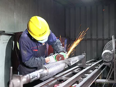
The two geometries need different channel-depth transitions, but both depend on controlled steel preparation, machining, heat treatment, surface processing and final inspection. Nanhaiya's equipment page lists CNC saw feed error at or below 0.1 mm, CNC lathes for workpieces up to 6 m, drilling and milling positioning accuracy of 0.02 mm, and five-axis machining for irregular flights and special structures.
Those machine capabilities support manufacturing. They do not set the order tolerance by themselves. The approved drawing needs datums, dimensions, tolerances, inspection methods and the mating barrel condition.
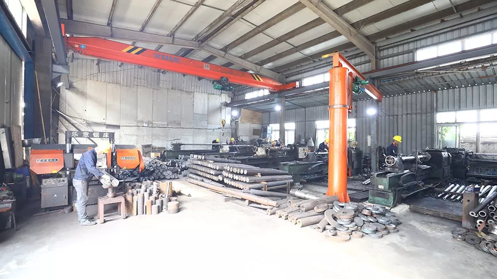

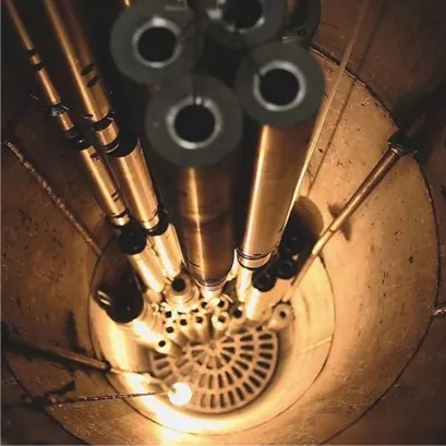

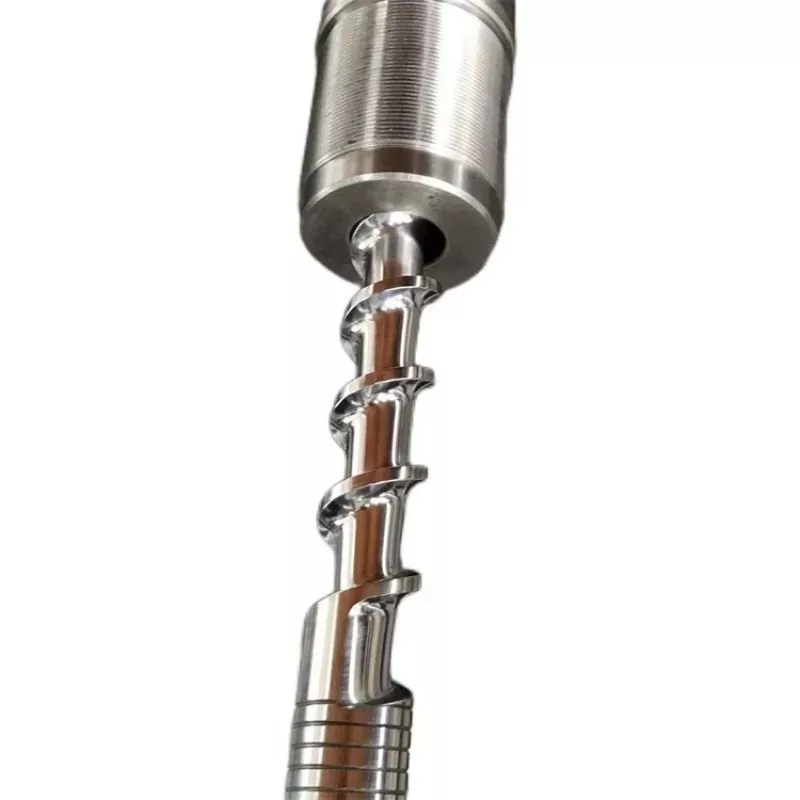

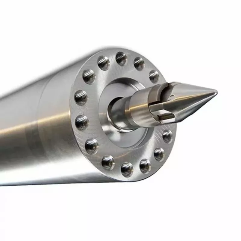
Our factory position: do not approve a gradual or mutant screw from a general product photograph. Approve the zone lengths, channel depths, compression transition, interfaces and inspection points on the drawing. The photograph proves appearance. The drawing controls the part.
For the full production sequence, see how screws and barrels are manufactured. The Nanhaiya production equipment page shows the factory and machining equipment used for screw and barrel work.
RFQ checklist for mutant and gradual injection molding screws
A good RFQ lets us separate the machine fit from the process redesign. Mark unknown data as unknown. If the old screw never made an acceptable part, say that clearly so the factory does not treat it as a geometry reference.
- Machine maker, model, serial and version
- Approved screw, barrel, tip and nozzle drawings
- Fresh screw OD and barrel ID wear measurements
- Drive connection, thrust face and axial datums
- Every resin maker and exact grade
- Crystalline, amorphous or mixed production list
- MFR or MVR with test temperature and load
- Filler, fiber, recycled content and additives
- Water-content result and drying process
- Actual part shot weight by material
- Machine maximum shot capacity and density basis
- Cycle time, cooling time and recovery time
- Screw speed and back-pressure profile
- Barrel setpoints and measured melt temperature
- Motor load or plasticizing torque if available
- Cushion and shot-weight variation
- Part dimensions, defects and rejection data
- Current screw profile and known problems
- Required material and inspection records
- Quantity, destination and required delivery date
- Installation and commissioning support
- Contract warranty and remedy requirements
| If the buyer says | What Nanhaiya still needs |
|---|---|
| "The machine is a 500-ton press" | Plasticizing-unit version, screw and barrel dimensions, shot use and resin |
| "We mold nylon" | Exact PA family and grade, moisture, glass percentage, shot and defects |
| "Recovery is too slow" | Cycle, cooling, recovery definition, speed, back pressure, temperature and load |
| "Copy the old screw" | Evidence that the old profile met quality and cycle, plus the original drawing |
| "Make it bimetallic" | Wear mechanism, damaged zone, barrel surface, layer coverage and inspection plan |
| "We need the fastest screw" | Accepted melt, part quality and machine-duty limits at the target cycle |
Nanhaiya's service process starts with material, machine and capacity diagnosis, followed by parameter matching such as diameter, L/D, groove depth and material. The site also lists installation guidance, troubleshooting, maintenance support, 24-hour response and a solution within 48 hours. Put project-specific support and warranty terms in the contract.
Test the new screw against the old production baseline
Build the acceptance plan before the screw is manufactured. Use the same resin lot where possible and record the old screw under a stable, known condition. If the old screw is too worn to form a useful baseline, state that and use an agreed production target instead.
- Freeze the test material. Record grade, lot, preparation, MFR or MVR condition, filler, moisture and drying.
- Define the machine state. Identify the screw, barrel, tip, nozzle, mold, heater and drive condition.
- Set the comparison points. Use agreed screw speed, back pressure, shot, cushion, barrel profile and cooling cycle.
- Wait for a stable process. Agree the number of cycles and the event that restarts the stabilization period.
- Capture synchronized data. Record recovery, melt temperature, load, cushion, shot weight and part results over the same cycles.
- Apply limits. Stop or reject the point when temperature, drive load, degradation, dimensions or another approved condition moves outside its window.
- Save the accepted baseline. Keep the settings, averages, variation, samples and component inspection records for future maintenance.
| Acceptance item | Useful pass condition |
|---|---|
| Mechanical fit | All interfaces, movement and clearances match the approved drawing and machine |
| Recovery | Plasticizing finishes inside the agreed cycle window without drive overload |
| Melt condition | Temperature and visible melt quality stay inside the approved range |
| Repeatability | Cushion, shot weight and part results hold the agreed variation |
| Part quality | Dimensions, appearance and required tests meet the part specification |
| Surface condition | No abnormal scoring, contact, coating damage or material hang-up after the test |
| Documentation | Drawing, material, treatment and inspection records match the delivered identity |
The choice is complete only after molding: the correct profile is the one that prepares an accepted melt inside the cycle while keeping the drive, temperature and wear duty under control. The shorter compression section is not automatically faster in useful production. The longer one is not automatically safer.
Frequently asked questions
What is a mutant injection molding screw?
On Nanhaiya's product page, mutant means an abrupt or step-change compression profile. Its compression section occupies about 5% to 15% of total screw length, and channel depth changes quickly between the deep feed section and shallow metering section. The short transition produces intense compression and shear over a short distance.
What is the difference between mutant and gradual injection molding screws?
The main difference is how channel depth changes through the compression section. A mutant screw makes that change over about 5% to 15% of total length. A gradual screw uses a long, continuous transition, typically 40% to 60% of total length on Nanhaiya's page. This changes melting rate, shear history, recovery behavior and melt-temperature uniformity.
Which resins are starting points for a mutant injection molding screw?
Nanhaiya lists PE, PP, PA, POM and PTFE as applications for the mutant design because these are crystalline or semi-crystalline materials with a more defined melting transition. The exact grade, viscosity, filler, moisture, shot use, cycle and quality requirement still need review before the geometry is approved.
Which resins are starting points for a gradual injection molding screw?
Nanhaiya lists rigid PVC, PS, PC, PSU and ABS for its gradual design. The long compression section gives a smoother change in channel depth and a gentler plasticizing path. The resin supplier's processing data, moisture requirement, additive package, part quality and cycle still control the final selection.
Can one injection molding screw run both crystalline and amorphous resins?
A general-purpose geometry may process several resins, but it is a compromise. List every approved grade and the production share of each one. Then compare recovery time, melt temperature, shot repeatability, color or degradation risk and wear. A dedicated screw is easier to justify when one demanding material controls quality or cycle time.
Does faster screw recovery prove that the mutant screw is better?
No. Recovery time matters only if the screw finishes plasticizing inside the cycle and the melt remains uniform. Compare recovery time with melt temperature, back pressure, screw speed, cushion, shot-weight variation, visible defects and part results. A faster recovery that raises degradation or variation is not an improvement.
What information should be sent for a mutant or gradual screw quotation?
Send the machine model and version, approved screw and barrel drawings, screw tip and drive interfaces, every resin grade, MFR or MVR test condition, filler and recycled content, moisture and drying data, shot weight, maximum shot capacity, cycle and recovery time, screw speed, back pressure, temperature profile, defects, wear map and required acceptance records.
What material and surface data does Nanhaiya publish for these screws?
Nanhaiya lists 38CrMoAlA steel, HB260 to 290 quenching hardness, HV900 to 1100 nitriding hardness, 0.5 to 0.8 mm nitriding depth, nitriding brittleness at grade 1 or below, Ra0.4 surface roughness, 0.015 mm straightness, HRC55 to 62 alloy hardness and 0.8 to 2.0 mm alloy depth. The order must identify which values apply to the selected construction and how they will be inspected.
Sources checked for this guide
- Nanhaiya: Mutant Injection Molding Screw
- Nanhaiya: Gradual Injection Molding Screw
- Nanhaiya: Injection Molding Screw category
- Nanhaiya: Production Equipment
- Nanhaiya: Service Process
- ISO 294-1:2017: Injection moulding of thermoplastic test specimens, general principles
- ISO 294-4:2018: Determination of moulding shrinkage
- ISO 1133-1:2022: Determination of MFR and MVR
- ISO 15512:2019: Determination of water content
- ISO 10350-1:2025: Comparable single-point data for moulding materials
Nanhaiya product geometry, application, dimensional-range, material, surface, factory and service data came from the live company website. ISO pages were used for the scope of the named test and data standards. The quotation, drawing, resin supplier data and acceptance plan control the final project.