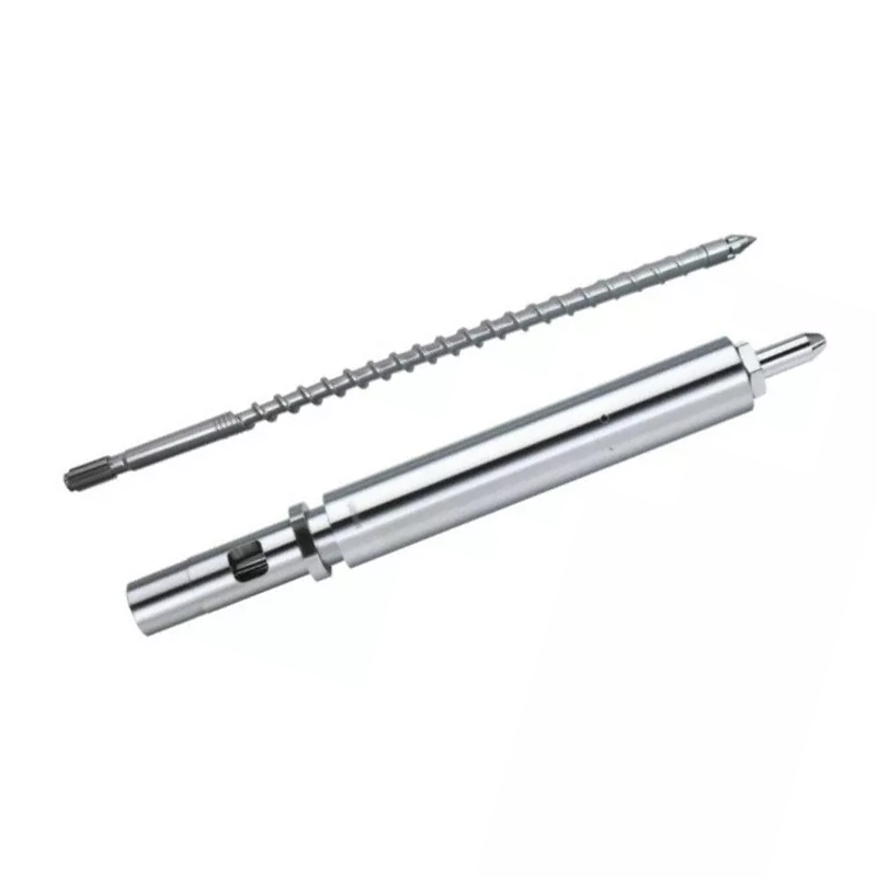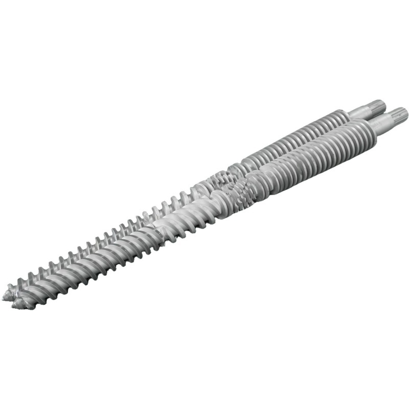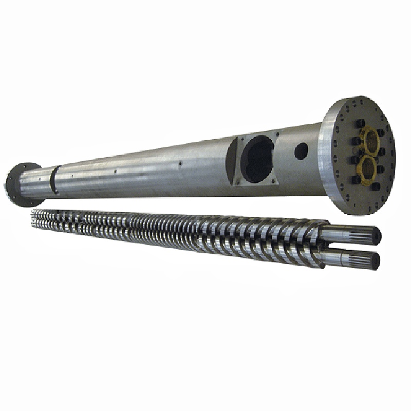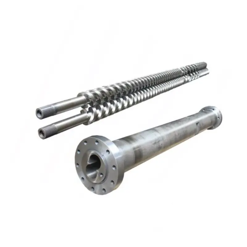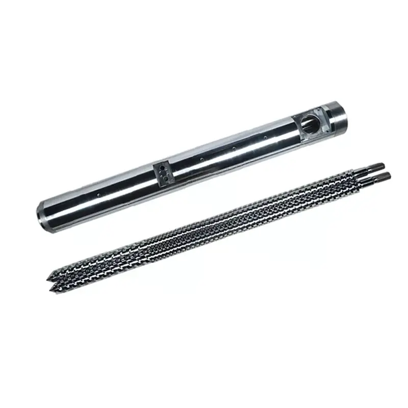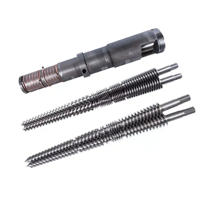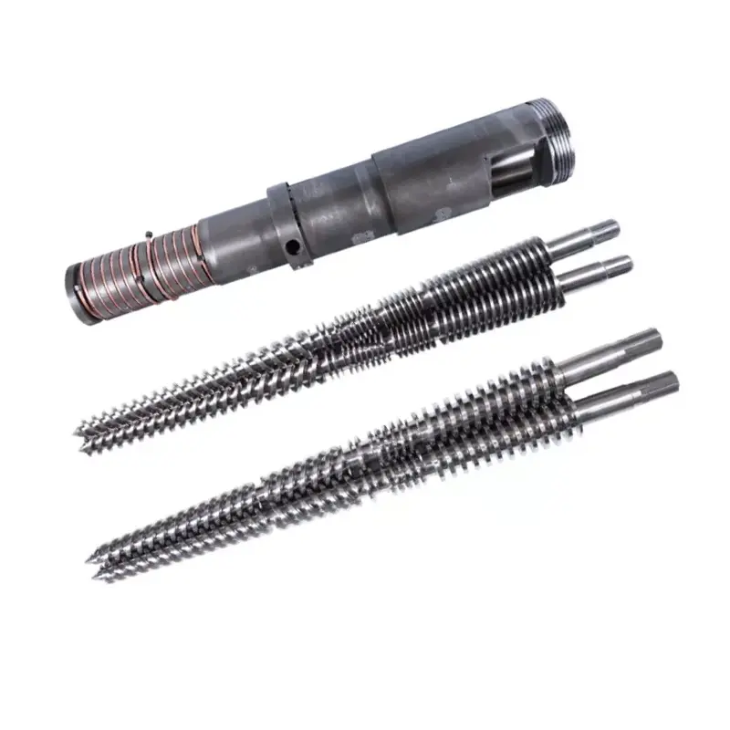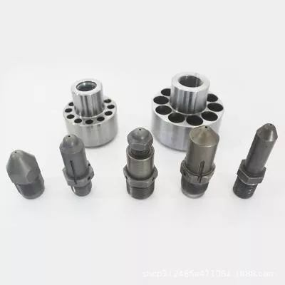

A twin screw set has more than one working gap. To make a sound repair or replacement decision, map each screw, each barrel lobe, the intermeshing relationship and the machine interfaces under one controlled reference.
Measure parallel twin screw and barrel wear as a matched system. Record both screws at named axial stations, both lobes of the figure-eight bore in defined directions, screw-to-screw clearance, center distance, phasing and axial fit. Compare the map with the approved drawing. Symptoms can trigger inspection, but measurements decide whether to replace screws, barrel or the complete set.
A parallel twin screw does not have one universal clearance
On a conventional single screw, diametral clearance is often expressed as barrel inside diameter minus screw flight outside diameter. Radial clearance is half of that difference. Our single screw wear measurement guide explains why the axial stations and definitions still have to match.
Local diametral relationship = corresponding barrel dimension minus corresponding screw outside diameter
Local radial relationship = local diametral relationship divided by 2
This arithmetic does not describe the complete geometry of an intermeshing twin screw set.
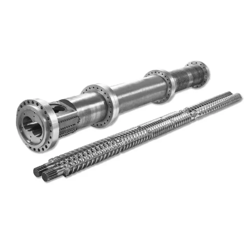
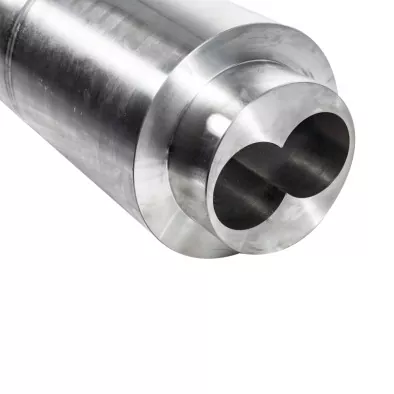
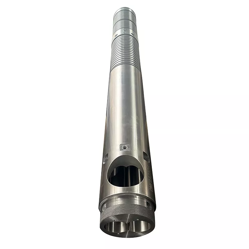
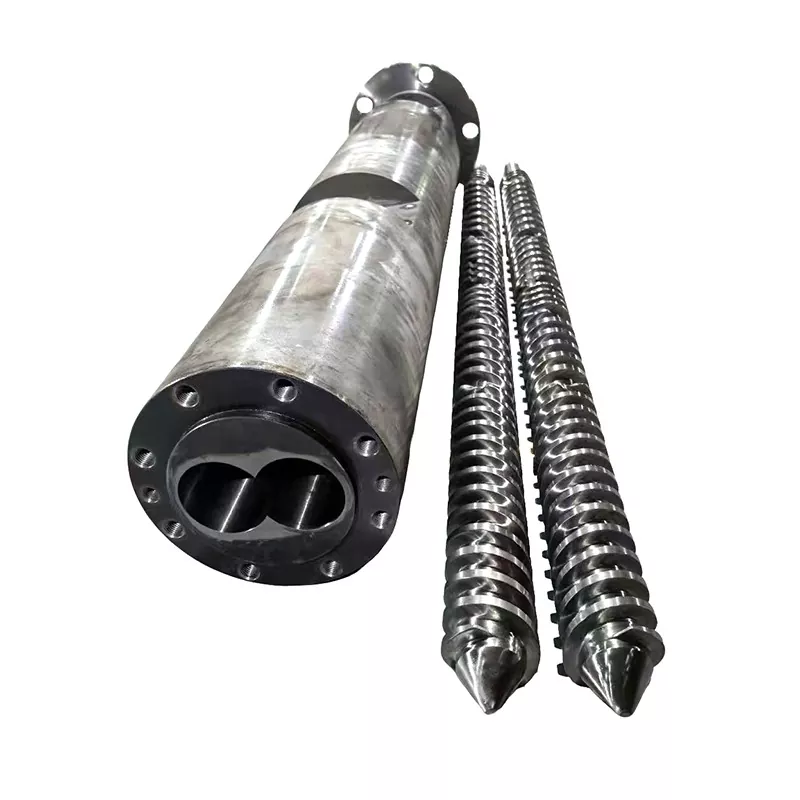
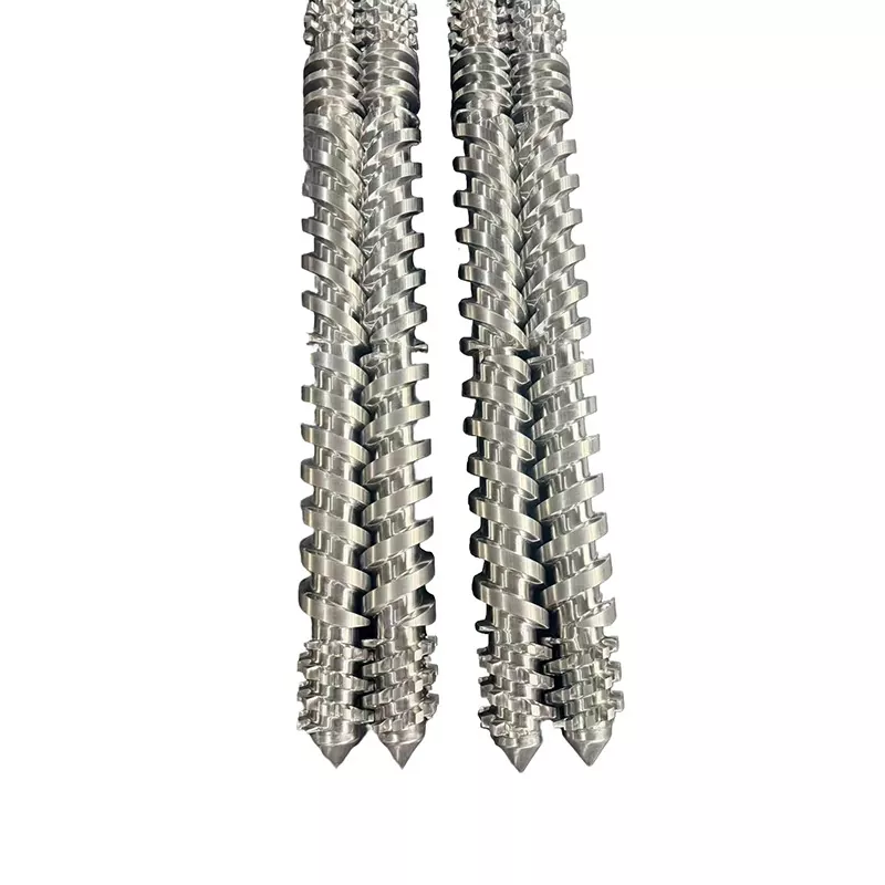
A parallel twin screw adds the second screw, an intermeshing region, a center distance and a timed angular relationship. The barrel is normally a figure-eight profile rather than a single round bore. Wear can also be different in the left and right lobes and on opposite faces of the flights.
The measurement file should therefore separate at least five relationships:
- Each screw's outside profile to its corresponding barrel lobe.
- Screw-to-screw clearance through the intermeshing region.
- Center distance and the position of both barrel lobes.
- Rotational phasing, handedness and left or right screw identity.
- Relevant axial clearances, thrust faces, spacers and end positions.
Our factory view: a buyer who asks for “0.3 mm clearance” without naming the surfaces has not given us an executable requirement. We ask whether that number is diametral, radial, interflight, side, tip or axial clearance, where it is measured and at what condition. Guessing here can create metal contact or leave the new set loose.
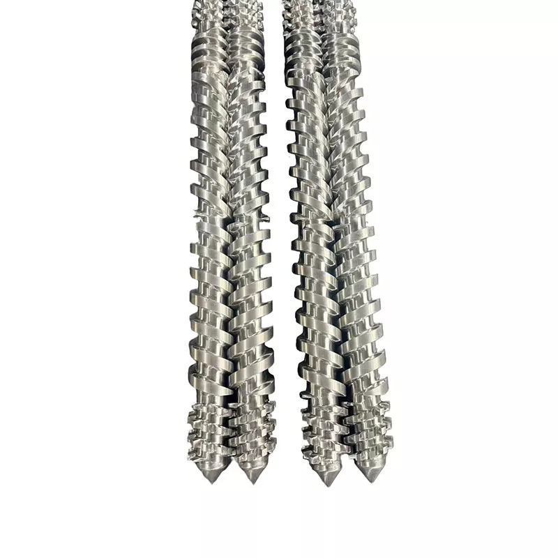
Preserve assembly identity before pulling the screws
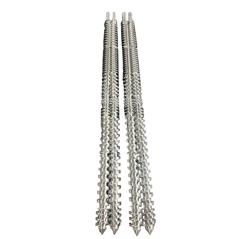
Measurements lose value if the left and right screws are mixed up or the phasing reference disappears during removal. Before loosening the assembly, photograph the drive end and discharge end. Mark the viewing direction used to describe rotation, then label both screws, shafts, spacers and timing marks.
Record whether the machine uses co-rotating screws or counter-rotating screws. Also record whether the screws are one-piece or assembled from elements. Do not assume two screws with similar outside dimensions share the same hand, spline, order or timing.
Use the machine maker's removal instructions and preserve every locking and timing feature. If the pair cannot be turned under the approved procedure after reassembly, stop. Applying drive torque to overcome an unknown interference can turn an identification error into damage.
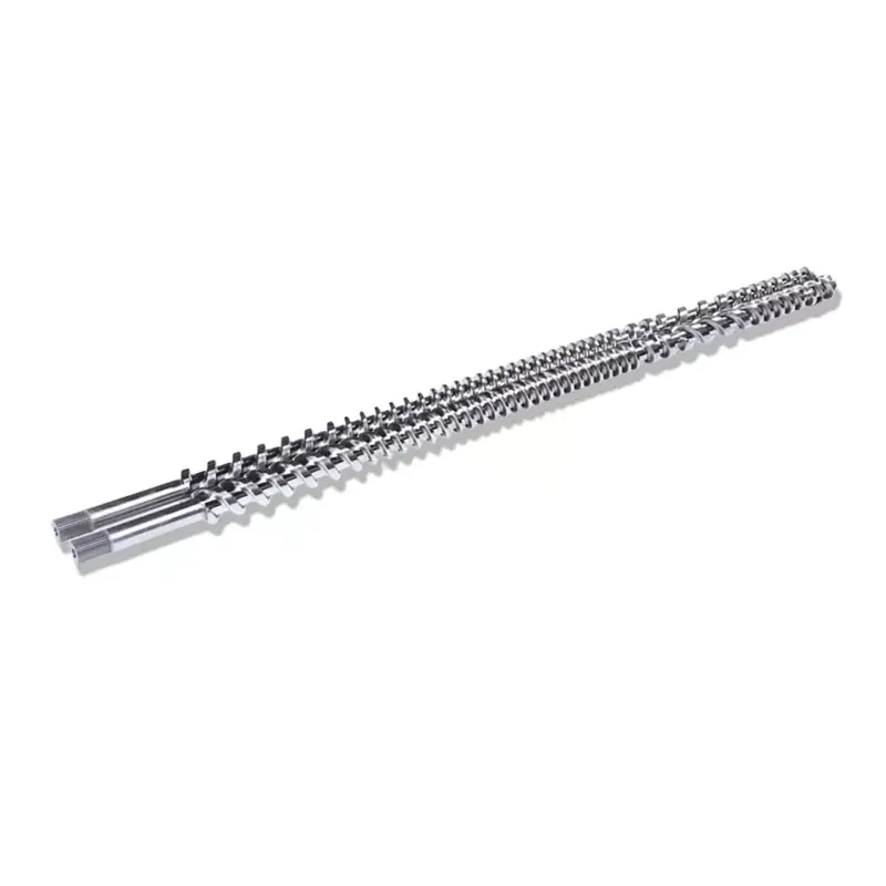
Build one coordinate system for both screws and both lobes
Clean the components without removing evidence of scoring, coating loss or pitting. Let the parts reach a stable inspection temperature. Establish a zero point at a named end and mark axial stations that can be repeated on the screw pair and barrel.
Add stations before and after geometry changes, feed and vent openings, mixing regions and the pressure-building end. At each station, identify left screw, right screw, left lobe and right lobe. Record multiple angular directions when the method allows, because a single diameter can hide ovality or one-sided wear.
| Field | How to identify it | What it reveals |
|---|---|---|
| Axial station | Distance from a defined feed or discharge datum | Where wear concentrates along the process section |
| Screw identity | Left or right, with the viewing end stated | Asymmetric flight wear and pair integrity |
| Screw profile | OD, root, tip or flank value with method and angular position | Loss of metal on the working surfaces |
| Barrel lobe | Left or right lobe, direction and measuring plane | Enlargement, ovality and local washout |
| Intermeshing relationship | Named surfaces, angular position, phasing condition and method | Risk of excessive gap or mechanical interference |
| Surface condition | Numbered photograph tied to the station map | Scoring, pitting, coating loss, deposits and contact marks |
| Reference value | Approved drawing, new-part report or agreed design baseline | How much the geometry has changed |
Coperion's published barrel diagnostic method requires its barrels to be clean and cool, then uses bore measurement and high-resolution video inspection on certain ZSK and STS sizes. Your machine and inspection tools may differ, but the approach demonstrates why dimensional and visual evidence belong in the same report.
Do not invent resolution by adding decimal places beyond the instrument and method. Record the instrument, calibration status, support condition, inspection temperature and operator or inspection record. A repeatable map with honest uncertainty is more useful than an impressive spreadsheet built from ambiguous points.
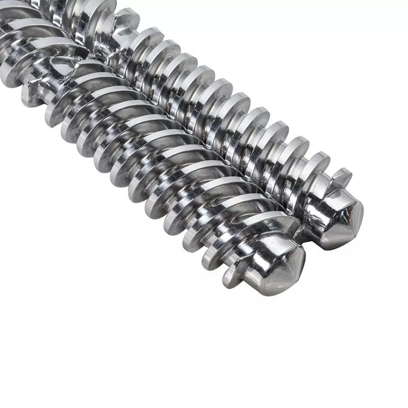
Have a removed twin screw set ready for review? Send the assembly drawing, left and right identification, station map, photographs and operating history. We can discuss what must be preserved and which areas need closer measurement.
Send the wear mapView parallel twin screw productsUse line behavior to choose inspection locations, not to declare failure
Falling output at the same screw speed, unstable pressure, changing load, poor dispersion, unmelted material and recurring product defects can justify inspection. They can also come from feeding, formulation, heaters, sensors, venting, a restricted die or a drive problem.
Save an operating baseline before changing several settings at once. Record actual feed rate, screw speed, load or torque indication, pressure, zone settings, measured melt temperature when available and finished-product checks. Compare the same formulation and downstream setup.
The Japan Steel Works notes that worn twin screw elements can reduce throughput and dispersion and may contribute to serious screw-shaft or gearbox failure. That is a good reason to inspect early, but the symptom still needs to be connected with a physical condition on your machine.
If a line returns to normal after correcting feeder calibration or a blocked vent, we would not sell wear as the diagnosis. If the process remains unstable and the measurement map shows a matching local clearance increase, the replacement case is much stronger. The goal is to solve the production problem, not to win an order for the largest set.
| Observed pattern | Process checks before condemnation | Physical evidence to seek |
|---|---|---|
| Output falls at unchanged speed | Feed accuracy, bulk density, recipe and die restriction | Local bore enlargement, flight wear and clearance change |
| Pressure or load becomes unstable | Feeding, temperature control, venting and downstream restriction | Uneven left/right wear, deposits, damage or contact marks |
| Dispersion or melt quality declines | Material lot, additive dosing, mixing configuration and temperature history | Wear at the intended mixing surfaces or wrong installed elements |
| Metallic noise or sudden torque rise | Stop under the machine procedure and inspect drive and alignment | Fresh contact marks, bent parts, phase error or foreign material |
| Rapid repeat wear after replacement | Material contamination, alignment, assembly, operating limits and surface selection | Repeated location and direction of damage |
Decide what to replace from the matched report
A screws-only replacement is reasonable when both barrel lobes remain within the approved geometry, the center relationship is sound and the wear cause is understood. A barrel-only replacement can also be justified when the screw pair remains acceptable and compatible with the restored bore geometry.
Replace the matched set when both sides are worn, the reference geometry is uncertain, or a new component would still run against a damaged partner. If the wear pattern points to misalignment, phasing error or foreign material, remove that cause before installing new parts.
| Measured condition | Likely scope to evaluate | Required safeguard |
|---|---|---|
| Screw pair worn; both lobes within the approved limits | Repair or replace the screws | Confirm the rebuilt or new geometry against the retained barrel |
| Barrel lobes worn; screws within the approved limits | Qualified barrel repair or replacement | Verify compatibility with both retained screws and center distance |
| Both screws and barrel worn | Matched screw and barrel replacement | Approve one controlled drawing set and inspection plan |
| Localized scoring or one-sided contact | Cause investigation before component selection | Check alignment, bearings, shafts, phasing and contamination |
| Geometry acceptable but duty changed | Process and geometry review | Define the new material, output, machine limits and product acceptance |
Do not use a generic internet multiplier as an automatic replacement limit. Diameter, screw type, machine design, material and product tolerance all matter. The original build drawing and machine maker's service criteria should control the decision.
For broader symptoms and repair choices, see our screw barrel wear and replacement guide. This twin-specific page adds the left/right, lobe, center and phasing information that a conventional single-bore inspection does not cover.
Use the wear location to specify the surface
Nanhaiya's parallel twin screw products include PVC, PE, PP, rubber, plastic, compounding and granulation applications. Material duty varies across that range. Glass fiber, mineral filler, pigment, recycled contamination and corrosive constituents should be stated by grade and loading.
Our co-rotating and counter-rotating product pages list the same core reference values: 38CrMoAlA, heat-treatment hardness of HB260 to 320, nitriding hardness of HV950 to 1000, nitriding depth of 0.50 to 0.70 mm and nitriding brittleness of grade 1 or lower. They also list Ra0.4 and screw straightness of 0.015 mm.
Available product values also include chrome hardness of HV 950 or higher at 0.05 to 0.10 mm thickness, and bimetal hardness of HRC60 to 65 at 2.0 to 3.0 mm depth. HV and HRC use different scales, so the largest printed number does not identify the better option.
| Finding from the wear map | What to define in the new specification | What not to assume |
|---|---|---|
| Flight tips lose material in a filled process zone | Protected flight locations, treatment or alloy, layer depth and final geometry | Every zone needs the same upgrade |
| One barrel lobe wears more than the other | Lobe map, alignment and center checks, then barrel protection | Harder material alone will correct misalignment |
| Pitting or surface loss | Material chemistry, cleaning history, affected zone and compatible surface system | All surface damage is abrasive wear |
| Contact marks repeat on one face | Phasing, straightness, shaft, bearing and assembly review | The screw profile is the only cause |
| Uniform wear after long stable service | Original geometry, measured change and required maintenance interval | A redesign is automatically necessary |
battenfeld-cincinnati recommends wear measurement once a year or after 6,000 operating hours in its service guidance for single, conical twin, parallel twin and planetary extruders. Treat that as one supplier's planning reference. Lines processing severe fillers or showing a fast wear trend may need a different interval.
Turn the inspection file into a manufacturable order
The quotation package should contain the machine maker and model, approved drawings, material formulation, operating record and wear map. Identify whether you want a faithful replacement, repair evaluation or geometry change. If performance must improve, state the measurable target and the machine constraints.
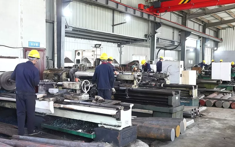
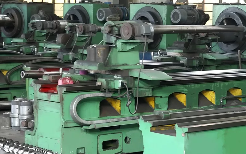
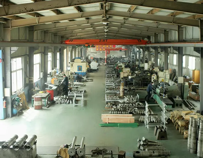
Drawing control matters as much as nominal size. Nanhaiya's production equipment page lists CNC drilling and milling positioning accuracy of 0.02 mm, CNC lathes for workpieces up to 6 meters, and five-axis machining for irregular flights and special flanges. Those capabilities still need an unambiguous drawing and inspection plan.
We will question a drawing when the specified clearance conflicts with the worn sample or when left and right information is missing. That is part of manufacturing responsibility. A signed drawing revision is cheaper than discovering the disagreement at installation.
Need a replacement scope before you request prices? Send the old-part report and operating problem first. We can help separate drawing questions, wear evidence and material selection before the commercial comparison begins.
Request a replacement reviewOpen the inquiry pageVerify fit first, then verify production
Incoming inspection should confirm part identity, drawing revision, left and right labels, material documents, specified dimensions and protected surfaces before installation. Keep the shipping and inspection record tied to the component serial or pair identification used in your plant.
Follow the extruder maker's assembly, alignment, lubrication, heating and start-up procedures. Confirm the pair's required free movement only by the approved method. Do not use the drive to force an unexplained tight position.
Commission with the agreed material, feed arrangement and die. Record output, screw speed, load or torque indication, pressure, temperature behavior, vent condition and finished-product quality. Compare against the acceptance condition, not against a brief no-load rotation or an easier resin.
Ask Nanhaiya to review your twin screw wear file
Send the machine drawing, left and right screw identification, rotation viewpoint, phasing information, center distance, wear map, material recipe and operating record. Tell us which symptom prompted the inspection and whether your priority is restoration, longer wear life or a new process duty.
Email drawings and measurementsDiscuss on WhatsAppView parallel twin screw products
Zhoushan Nanhaiya Plastic Machinery Co., Ltd.
Products: Co-rotating parallel twin screw barrels | Counter-rotating parallel twin screw barrels | PVC parallel twin screw barrels | Rubber and plastic parallel twin screws
Email: info@nhyscrew.com
Phone: +86-13505809643 | Mobile: +86-13587082002
Block C, No. 2 West Section, Xingzhou Avenue, Dinghai District, Zhoushan City, Zhejiang Province, China.
Service information | Production equipment | Company profile | Contact us
Frequently asked questions
What is parallel twin screw barrel clearance?
It is a set of geometric relationships, not one universal gap. A useful specification distinguishes each screw's clearance to its barrel lobe, screw-to-screw clearance through the intermeshing region, center distance, phasing and any relevant axial clearance. The approved machine drawing defines the target values and measurement methods.
Can I calculate twin screw clearance as barrel ID minus screw OD?
That subtraction can describe a local diametral relationship only when the two values refer to corresponding locations and a defined bore geometry. It does not describe screw-to-screw clearance, intermesh, phasing, center distance or an out-of-round figure-eight bore. Do not use it as the only twin screw acceptance value.
How many places should I measure on a twin screw and barrel?
There is no universal count. Create enough axial stations to cover the feed, melting or compression, mixing, venting and pressure-building regions, then add stations around visible damage or geometry changes. Use the same station names on both screws and both barrel lobes.
What should be recorded before removing parallel twin screws?
Record the installed left and right positions, rotation viewed from a named end, handedness, timing or phasing marks, shaft connections, spacers and axial order. Photograph the drive and discharge ends, label every part and preserve the machine maker's removal procedure.
Can I replace only the twin screws and keep the old barrel?
Yes, when the barrel bores, center relationship and surface condition remain within the approved limits and the cause of screw wear is understood. If the barrel is enlarged, oval, scored or misaligned, new screws alone may leave excessive or uneven clearance. Base the decision on a matched measurement report.
How often should parallel twin screw barrel wear be measured?
Set the interval from the machine maker's maintenance plan, material severity, operating hours and the line's own wear trend. Battenfeld-cincinnati publishes one year or 6,000 operating hours as its service recommendation, but that is a planning reference rather than a universal replacement limit.
Does Nanhaiya publish one standard working clearance for every parallel twin screw?
No single working-clearance value covers the full range. Nanhaiya publishes product values for material, heat treatment, surface hardness, layer depth, roughness and screw straightness. The functional clearances still need to be defined on the approved drawing for the specific machine and screw pair.
What should I send for a replacement parallel twin screw barrel quotation?
Send the machine maker and model, approved drawings, left and right screw identification, rotation viewpoint, center distance, connection and flange details, material formulation, output and operating record, axial wear map, surface photographs, failure history and required inspection documents.
For system selection and operating principles, continue with our parallel twin screw extruder guide or the broader twin screw extruder selection guide.